Oz NDY – Return Air Plenum Issues – Part 2
Following a site mtg we have a much clearer understanding of the issue at hand. The mech contractor, Envar, have sent us a mark-up (as requested) of the location and sizes of all holes made by the builder to initially increase air flow; which it has.
So why are we not getting the correct RA flow to the AHU? It also came to light that there is heavy congestion (as shown in fig 1) around a services (namely ducting) choke point (about 1 m2) which is restricting the RA flow. The congestion issue is unique to this level due to the balcony which a severely reduced the overall free area by approx. 1 m2. So, in theory we could turn the closest partition wall into a sieve and we would still have the problem. We can’t practically do this though as there isn’t enough space in this particular partition.
Therefore, we still need to get the balance of air from somewhere which the AHU fan is drawing in. So with the choke point in mind this will have to come from the SA side (the corridor) outside the plantroom. This corridor is open to the large open-plan office area but air flow either end is stopped by pneumatic actuated doors (for security as these areas are sub-tenanted). So what? The makeup air would be mostly SA and not RA as intended. So how does this affect the CO2 levels?
Below I’ve recalculated the area of hole required which would be incorporate as either a door grille in the plantroom door, or, depending on size, it could turn out to be a complete louvered door.
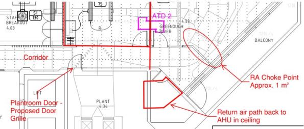
Figure 1. Return Air Choke Point in Plenum.
Calculations
A quick calculation to check the hole size required:
Q = 8.839 m3/s. This is the entire SA flow rate that is trying to get back to the AHU as RA.
A = 1 m2. The approx. area of free flow through the choke point.
Therefore, V = 8.8 m/s. That’s pretty quick and why it has also been reported that a few ceiling titles are flapping around near the exit hole from plenum into plantroom. These are being addressed by replacing with egg crate extract grilles.
If we want to achieve a steady flow rate of 5 m/s then this gives an A = 1.77 m2. Subtract from that the area we do have (1 m2) = 0.77 m2 hole required.
On a basic 2100 x 920mm door (leaving an edge of 100mm both sides) gives a door grille neck dimension requirement of 1100 x 720mm = 0.79 m2. That’s the ‘free air’ area needed where a louver or grille would require being 50 – 60% bigger to take into account the area lost due to the vanes. So, it would need to be 1.26m2, which is about 1800 x 720 = 1.29 m2 which equates to pretty much the entire door when you take into account the structural edges.
So what? It would require attenuation on the plant side of the door to mitigate plant noises transferring back into the corridor, which shouldn’t be heard too much anyway as it is just a corridor and the open-plan office area is actually through a central kitchen/restroom area.
To check this I spoke to our acoustic engineer and used the dB data. The corridor was reading 52 dB, I then added 25 dB for removal of the current door and then subtracted 5 dB for adding a louvered door with some attenuation on the reverse side. This results in 72 dB being heard in the corridor, which is about 22 dB over what it should be (50 dB being the norm). Therefore, this is a problem and exacerbated by the frequency range of the particular plant, which will be a low rumbling (low freq) which louvers still let through.
It would therefore be better to install an ATD above the plantroom door but this idea was discarded due to a large duct run right next to it running down the length of the corridor. This also means that we can’t put any more egg crate extract grilles in as the one currently installed sits no more than 10mm below the ductwork so this too will be restricting the RA.
The only other option I can see is putting in a large or two smaller ATDs through the wall area into the plantroom. But even this has its issues: is there free space on the other side of the wall? How far away is the AHU and can we fit a ATD in? Being the base build, will the building owner approve it?
I have also been informed the AHU has an economy cycle (which I should have expected) where the ambient OA temp dictates how much OA is used rather than wasting energy in cooling RA when there’s ‘free’ cool air available from outside.
ATDs
I made a point of mentioning the need for ATDs in the cut-outs. With the extra holes present no occupants have complained of cross-talk, therefore Envar suggested they would get the builder to tidy-up the holes and leave them at that. Ironically, it seems like any holes made in the partition wall don’t need attenuating due to the ductwork congestion.

Sounds like quite the ‘situation change’. Do you think it is just the variation for the full height walls that has caused this or do you think it has just compounded the effect of the RA path not being fully calculated in the initial design?
Tell me about it…I think it’s a combination of design challenges not quite working together as planned. You’ve got a base build complete with all its services which is then added to with supplementary services (predominantly air conditioning) due to the new fitout. This has created the congestion in the ceiling void which was then compounded by the late variation of full-height partition walls. This is all based on a RA system that is cheap, and you get what you pay for. I suppose this is the enjoyment of engineering; finding a way to resolve an issue no matter how challenging.