If Carlsberg did risk mitigation for piling
Bank Street – If Carlsberg did risk mitigation for piling
I attended a site visit to Bank Street at Canary Wharf this week. Arup are the design engineers and Laing O’Rourke (Expanded Piling) are doing the piling. The activities are mainly piling so far there have been an incredible amount of problems, solutions and wonderings to be discussed. I’ve attempted to highlight some here.
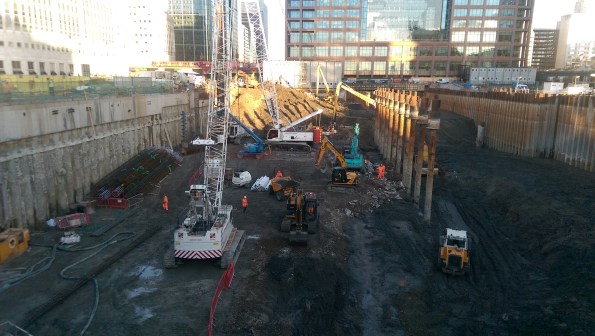
The current site – note central CHS piles for reference later.
CFA piling
Test pile
The plan was to install the tension piles for the main test pile but the rig being used could not extract the auger once it had reached toe level. The issue was found to be that as the top of the auger went below ground level the material on top of it tended to pack it in on top so trying to extract resulted in the mass of soil above the top of the auger being too great to remove. Therefore a longer auger, one that extended the full pile length was needed, and an equivalently long mast. This was realised and a new rig was used with success.
As part of the specification each pile installation was checked for the rate penetration with auger rotation. The aim being to get 10 rotations per metre. This reduces any flighting where soil material is dragged into the pile and therefore reduces the pile diameter. This worked well and the rig can be automatic to achieve this.

Example of getting the flighting penetration rate too slow or too fast.
Instrumentation calibration
This is not something I really picked up on while on site Two Fifty One but is really important, especially with CFA piling as one can’t look inside the casing to check the base.
Pressure gauge – CFA piling relies upon positive pressures when filling the pile as the auger is extracted. The positive pressure implies that the concrete is being distributed all around the bore to construct the pile. The rig on this site read 0.5bar so seemingly all was well. However, something was amiss – When it came to inserting cages they only went a few metres until it was found the pile had collapsed in. The strokes on concrete pump were counted to ensure the correct volume was being distributed into a 2metre cubed box. It wasn’t so a pressure gauge test was done on the rig sensor and it was found to be faulty. The pile was being under fed by about 20%!
After the many weeks of trying to get these piles sorted for the pile test, the rig (new one) and old rig instrumentation was mended. My advice, or what I would do now I know it, would be to ask to see some of this calibration going on if I were on site while piling is going on. Arup put these tests in their specifications to ensure everything is working which seems sensible.
Cased, rotary bored piles
Secant wall
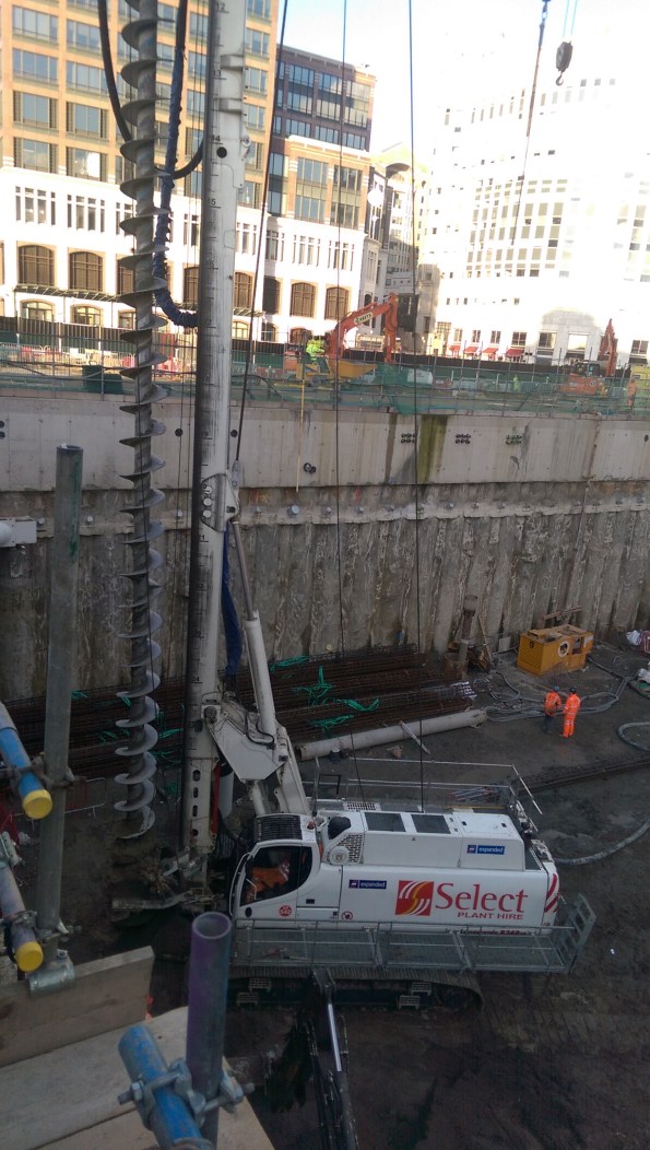
CFA rig with Secant wall behind.
Ground anchors along length of secant wall. Note which piles the anchors are in (female…?)
The secant wall was due to carry both horizontal and vertical loads. It was base grouted which is where the stiffness below the pile is improved, not ultimate bearing resistance, to reduce initial settlement. This is where the pile cures and sometime later the steel tubing inserted inside the cage is pressurised with water which cracks the bottom of the pile. [I have a photo on the way, but for now imagine a steel hose pipe running down to the bottom of the cast pile with a couple of holes in the bottom.] Grout is then pressurised inside the tube and in theory fills any voids around the base. A subsidiary check is to get a pressure to show that the grout is not just heading off somewhere. There should also be some pile uplift to prove base resistance. This was not always achieved which in theory would be a concern. But it was a secant wall so if uplift was achieved, would the piles have actually have been connected? The stratigraphy at the site is such that it is not far from ground to Thanet sands so working loads can’t all be taken in the shaft. Therefore it’s more important to understand about base resistance. One might question the point of doing a test with secant piles, other than with the confidence of reaching a certain pressure.
As a quick tangent, my colleague who worked on Cross rail, where penetration grouting was used, advised on the need to avoid over pressurising the base of piles because of the risk of heave. They only had 7m of soil above the base of the pile, let’s say 140kPa. 1 bar is 100kPa. Apparently you need 4bar to get the grout into the voids. Mmm turns out there was some heave!
Back to the site visit.
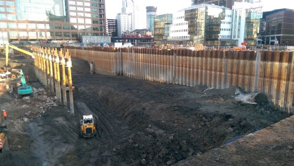
Double skin sheet pile wall
This was where the most fun occurred. 2 rows of sheet piles were installed to act as a self-supporting wall on one edge of the site.
![16838273893_3262acd6e2_o[1]](https://pewpetblog.com/wp-content/uploads/2016/02/16838273893_3262acd6e2_o1.jpg?w=595)
Near: Double sheet pile wall. This is filled with material then ties are placed and then the top section was concreted. Rear: Secant wall installed, reinforcement for capping beam can be seen.
Double wall cofferdam from the inside
The sheets were installed by pre-augering. Angela raised this as a question last year I think. Arup advised against it. As that was what the contractor wanted to do, Arup specified some come penetration tests either side of the piles to see what resistances were gained (minimum of 15 N value). A chart was presented down to the Thanet sands showing almost no resistance! The augering inside the piles had removed lots of soil and where it had influenced outside, it had reduced the soil strength to close to zero.
So what? The solution was to fill inside with concrete and grout the outside. Concrete was used to avoid having to go back and certify (if granular material was used it would probably have been difficult to achieve any compaction and may have failed further CPT tests, using concrete avoided that). This took months, was expensive and difficult to do underwater. Any plans to reuse the sheets anywhere below ground level are now out!
Summary
Firstly it was great to be back on site and see some piling elsewhere compared to Two Fifty One. The engineer had clearly been busy resolving problems but it seemed to be that most of the tests, checks and procedures were all sensible and go some way to mitigating what is really a pretty uncertain activity. One assumes all is well with the pile but really we have no idea. There is a balance between equipment, instrumentation and people. They kind of all need to chime together to reduce the risks. I feel that this visit was very useful confirmation of the sort of standards expected when piling in quite a range of issues.
More photos


Vibrating head with circular hollow section to push reinforcement cage to pile cut off level. We used a similar method at Two Fifty One, but without the vibrating head – this methods looks far easier but needs more equipment.
![20151111_DSC_0016_resize[1]](https://pewpetblog.com/wp-content/uploads/2016/02/20151111_dsc_0016_resize1.jpg?w=322&h=429)
The site before dewatering. Left: double sided cofferdam, centre: CHS piles shown above for orientation, right secant wall.


On the way in we saw piling under bentonite. Rig with digging bucket attached removing spoil. Bentonite silos (black), green objects in front are the cleaning chambers to remove granular material residues.

On the CFAs I suppose there was some form of low srain dynamic testing to check the quality of the piles ( for nexcking and bulging) . A test of whether you can get the cage down picks us the hopwlessly necked and perhaps not the badly necked?.
On the pre-auguering – I still don’t know the answer. On one of my jobs I had pre auger AND failure to get toe depth (who’d have thunk? ) I re analysed the thing and put in an observational scheme.
All I can say is the temporary state remained stiff enough- but I could find no guidance on strength and stiffness to use after pre-augering
Can’t be much left on the piling side of life that you haven’t seen! 🙂