CCB – Ft LEE Training Facility
The ‘museum’ is still behind schedule. 95% submission is due mid – late march, a 3 month delay on the original. A rendering of the building is below, with my portion of responsibility shaded.
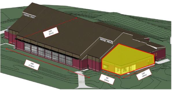
Ft Lee Training Facility
The larger space is largely progressed however the shaded portion, which is structurally separate, had not been looked at, other than producing a column grid and an interior plan. The promoter intends the space to be open plan admin and teaching space. Therefore a rigid frame layout is required instead of braced. This is comprised of lateral and gravity beams and columns, (with the latter being pinned at the ends, hence not transferring moment). I designed the frame keeping the lateral frames symmetrical as much as possible to reduce torsional effects induced by any wind or seismic loading. If there is not enough rigidity in the structure after running the seismic calculations I have enough ‘spare’ gravity columns which I can make into lateral columns to stiffen up the frame and retain some symmetry.

Structural Frame Design
The loading of the structure has been affected by the Protective Design Center (Sic) (PDC) who have said that the cold formed steel truss system proposed for the roof doesn’t meet blast requirements. This is strange because stud walls and metal decks, which also consist of cold formed steel, are adequate systems. To me this means that either they haven’t been able to test the particular roof truss system in question, or there is an issue with the truss connections. The roof system is ‘designed by others’ so options were to either specify a requirement for hot rolled angles to form the roof truss or provide a second roof. The first option would greatly increase the weight of the roof and affect seismic design as well as costs whilst the second (selected) requires joists and decking. That means that the load paths need to be considered and modelled appropriately. Instead of having the ‘high roof’ which will transfer the wind and snow loads into the frame, sitting across the joists it will sit directly onto the main frame. Modelling roof loading across the flat roof decking would incorrectly increase the joist size and would increase the costs unnecessarily. I will therefore model the ‘high roof’ loading as line loads running across the beam lines as shown below.
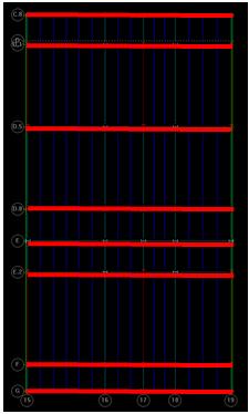
High Roof Loading Model
I will input the permanent and variable loads for the roof based on the relevant standards (in the same way as we get our values form the ECs) but I will also need to manually calculate and input the snow drift loads. These, along with the seismic loads have not been calculated for my portion of the building so I am grabbing as many design examples, codes and text books as I can, to handrail. The computer will automatically model the wind and seismic loading which I can cross reference with hand calcs.
Environmentally the site as a whole is legally required to maintain similar conditions to the pre-construction water run off conditions, in line with the Energy Independence and Security Act 07 (EISA 07). This ‘low impact development’ (LID) approach is managed by the civils (site development) department who will design in methods to ensure the targets are met. These targets will be set by the initial site assessment which will look at things such as hazmat risks (POL), asbestos water quality and quantity of run off.
The promoter will budget the costs of the designed measures (swales, pervious parking areas, filter strips, and vegetated buffers etc) which are required to maintain the site at or close to its pre-construction state. The estimated costs are entered as a separate line item on the form that is required to request project funds from congress and are based on 2% of the overall ‘supporting facilities’ cost. This policy is intended to ensure that all government projects have adequate funds available to cover any LID requirements. ‘Supporting facilities’ are anything that isn’t the constructed asset itself and includes such things as the electric, gas and sewer service costs, pavements, storm drains, ATFP and any other site improvement / demo costs. For this project the ‘supporting facilities costs are estimated to be $5.5 million, therefore implementing the LID measures has $110,000 budgeted. This will presumably form one of the constraints on the design. To me the figure feels low considering some of the effort that is required to treat water before it is discharged from site in line with EISA 07, however this line item will be added to all the others for the project and a 5% contingency added to it.
Building 8607 Renovation, Ft Meade. The Design Build RFP (aka ITT) sections are produced by the different departments in the Engineering Branch. I helped the costing effort by producing a rough schedule of quantities expected in the ATFP upgrades. I based this on drawings which were used in the upgrade of a similar project which used the alternate path method of hanging floors using tension rods in the event of a column removal.


With the odd exception most values required by the estimating department were in tonnes, so fixtures and fittings (bolts etc) had to be converted from individual units. Other bits of work, for example welding or demolition of walls, was required in linear or square feet. I was a bit stumped by how I should tackle the installation of the lift but was advised that a line saying ‘1 x lift’ was sufficient! Whilst I was happy enough with that it occurred to me that it would probably be a bit of a waste of time for me to do that because there are people who are much better placed to do it. My value came in understanding the structural components of the ATFP system and being able to dig into the weeds of that. The selected ‘preferred’ ATFP method has been based on the fact that it has been done before, and that is what has dictated the government estimate. However, the contractor may well decide to completely re-build the concrete framing and install a tie force method of ATFP while he’s at it. This could potentially mean that the government estimate is a long way off the contractor estimate which, if realised, will introduce a bit of risk into the tender process because it will increase the complexity, hence increase the duration, of the negotiation process. Having said that we had to start somewhere and using precedent seems as good a place as any in this instance.
Access Control Point, Ft Meade – This project is now due to start in July 16.

Hi Brad, how it the truss made – I have found that connections seem to draw lots of attention regarding durability be it corrosion or fire, so if welding is being used perhaps that is what’s being scrutinised. Who pays for the additional costs in design and the affect of the rest of the structure, assuming a weightier solution is required?
What sort of snow loads will your roof attract – the pitch looks steepish from the image so would be interesting to know.
I have seen a few seismic presentations recently and I learned that it is well out of my knowledge base – how are you going to do a hand calculation check or will you get someone in that field to verify/review your computer outputs?
Hey Damo, The truss is not in our design remit however all the ‘designed by others’ trusses I saw on site were welded. From what you are saying it appears that the connections will attract closer scrutiny by the PDC. I think the leaning is towards the truss and decking solution, although any additional costs will be paid for by the promoter. The Promoter (Govt Agency) has bid for the total project funds to congress. The total cost of the built assets and attributed site work is around $29m. On top of this will go a standard 5% contingency, which is where additional costs come from. Design costs of 4% and a supervision and admin fee of 5.7% are also included.
The snow is split into two load types, balanced and unbalanced. Because of the shape of the overall roof there is quite a lot of drift (unbalanced snow load) in an area of ‘aerodynamic shade!’ Basically this is where snow from the higher adjacent building is blown onto mine. This will obviously sit on top of a base (balanced) layer of snow which will form depending on the geography and building shape/ slope. The load is significant, especially in the unbalanced zone. Triangular loading shape of 200p.s.f (10kN/m2) reducing to 0 over 24′. So its easy to see why it causes structural failures in times of unusual weather. It also means I’m expecting some fairly hefty beams and connections in the unbalanced zone. The pitch is 3:12 so not too excessive. I’m doing the seismic modeling on the computer but I’m going to have a stab at the seismic calcs by hand. Firstly to try to understand whats going on, secondly to verify the output. Seismic calcs are fairly standard here so there is lots of literature and some handy cheat sheets.
Brad, thanks for the detailed reply. Interesting to see how the costs are added.
Regarding the snow loading – the UK, being a maritime climate, seems to adopt a single event principle rather than effects from an accumulation of multiple snow falls. I presume you are the opposite where you are – how do your design codes handle this. Is it a summation of events with an assumption for some melting or just addition on addition. If the latter is there risk of over designing everything, or were the recent events good evidence for designing for high loads?
The codes here specify for a 1 in 50 year event for which tables are produced for geographical areas. This general data is then used for the specific building case, taking into account such things as shape, height, adjacent structures, heating…etc. So in short no, it seems that the codes adopt a similar principle to the ECs. (both contain calculations for balanced and unbalanced snow loading)
I assumed that the key difference would be in the general ground snow loading. Looking through the codes some values are: 1.2kN/m^2 for Maryland, 0.24kN/m^2 for Alabama, 0kN/m^2 for Bahrain and 4.79kN/m^2 at a place called Goose Airport, Newfoundland. I did a quick calculation of “sk” from NA to 1993:1-3 and get a value of 0.5kN/m^2 for 100m ASL for the majority of the UK. (obviously this takes no account for any of the other factors I mention above but for a rough comparison probably does the trick.)
One thing that the US code does do however is include a ‘rain on snow’ surcharge clause which applies for situations where ground snow is less than 20psf. (1kN/m^2). In this instance a 5psf surcharge is added to roofs with slopes of a shallow pitch. Other than that the design approach seems similar. This takes into account the potential for a build up of ice on top of shallow roofs and the additional loads implied.
Brad,
Thanks for delivering something that looks like engineering from the USA! The Ft Lee building is interesting – a moment resistant frame you say. What are the connection details like at the column bases and how are the footings set out? Pad strips? This is all going to be very interesting withy seismic action and a high snow load!
The additonal budget for LID is interesting, presumably the cost of ‘traditional’ drainage forms part of the ‘suporting infrastructure’ base costs and the additionl cash is then uplift for additional works to deliver the LID. i.e it might not sound like much but it is additional over rather than total allocation.
I have to say the hangers used to provide alternate load paths look to be pretty pointless. If the cloumn next the the hangers goes so will the hangers even if they’re going to be concrete cased (which I presume they will be for fire protection?). If they are encased, they might provide additional stiffness to each column sufficient that there is adequate additional capacity to cope with removal of an adjacent set. But who knows without a model and some numbers. Surely if the contractor wanted to demolish and rebuild it would be because he could do so for less cost (or more profit) than using additional elements. If he can do it for less his price, if not the same as allowed for, would be better than the allowance and so presumably easy enough to agree!