Archive
Up the creek, without a paddle
So, whoever said demolition would be easy, obviously has not visited this site. The newest problem that we have faced involves a nearby hotel (a key stakeholder in the development), a blocked foul drainage pipe and an excavation full of yesterdays dinner!
Last week there was a distinct smell of faeces in a nearby pedestrian street. The PM mentioned this to the Construction Manager and asked him to investigate. The next day, said CM was moved to a new job (polite way of sacking someone in the civilian industry). Therefore the investigation never happened.
Yesterday morning the hotel manager contacted us through the liaison manager for the project to inform us of a drain that was backing up just outside of the hotels loading bay. The hotel is located uphill from the demolition site and the previously mentioned pedestrian street (a pedestrian street that was created as a temporary diversion at the start of this demolition).

The hotel loading bay – In the background the drainage SC
Carillion, being the forward leaning, considerate constructors that they are, offered to investigate. This consisted of a drainage sub-contractor opening a drain cover on the pedestrian street and saying “Oh yeah, that’s full of Sh*t”. They had already identified the bottom of the private drainage run, that was clear, so the problem lay somewhere in between the two. They are coming back this morning to try to jet the blockage and get the flow moving.
Three tanker loads have been removed from the drain to buy some time.
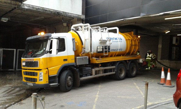
First tanker from Burntwood SC
The cause of the blockage is yet to be established, although we think it was probably the SC who installed the pedestrian street and potentially damaged some of the pipes or left debris inside. However, previous drainage reports from prior to the street being installed, all mention debris in the system.
Votes on causes please:
- Debris from street construction.
- The hotel has eventually blocked it with their own fat/waste from kitchens and toilet paper from rooms.
- The flow has reduced to a level below that required to keep the drains clear. The hotel is the top of the run and it’s occupancy has dropped since demolition started, the office block that also connects to the drain is now unoccupied.
- Other.
In other news:
Laura is pregnant again – due mid November.
I have built a huge deck in my Garden – due May bank holiday!
Don’t mention Heathrow!
Ever wondered where your bags go after you drop them off at flight check in? Probably not, however below the glamour of the airport departure lounges, there exist dungeons otherwise known as ‘baggage halls’ where kilometres of conveyors and machines screen and sort your bags to their appropriate flights.
Having spent the past two weeks immersed in the baggage halls of Gatwick Airport, I can say with some confidence that I must be the RSME’s new expert on airport hold baggage systems (unless Jim can still remember from his time here?). This blog very briefly introduces the Programme and my role.
The Programme
Every bag that is loaded into an aeroplane’s hold must be scanned for suspicious substances prior to loading. To meet the latest EU regulations, Gatwick must (barring any Brexit effects) upgrade all 30 of their screening machines prior to 2018 at about £1m a piece. Unfortunately it is not a simple case of swapping the newer ones in for the older ones. Due to increased power and cooling demands, as well as severely restricted access to the machines, a programme of enabling and upgrade works to all the current baggage handling systems is required. The budget of the Programme is £139m and it is split into 9 different projects, all to be delivered with no interruption to daily baggage operations.
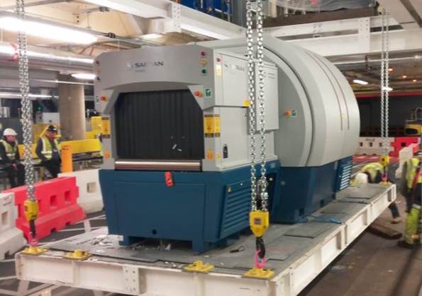
Pilot project – 6 tonne Explosive Detection System being lifted into position for trialing.
My role:
As the Mechanical, Electrical and Plumbing Building Services ‘specialist’ within the Programme team, I will support all of the nine Projects by managing a) the MEP designers during design stages and b) managing the MEP sub-contractors during construction stages. Work on the first of the nine projects is due to start in July so I’ll be concentrating on design reviews and contractual work up to then.
![]()
Typical baggage hall conveyor – these bags are in ‘quarantine’ – they have gone through the explosives scanner but await decision if they are safe or not.

Typical sorter – once scanned, bags are individually loaded onto trays that then flip your bag into the bin designated for your flight. All governed by barcode readers and PLCs.
In terms of experience so far, I found that the principle designer has fudged their concept lux lighting level calc’s worse than a Phase 1 PET student, and that Heathrow is referred to only as ‘the other place’.
A genuine offer; if anyone is flying from Gatwick over the next year, please do give me a shout and I can go into more detail over a departure lounge coffee!
CPT GREAT BRITAIN (or so my email address says)
Right, my first foray into the ‘blogosphere’! I understand I’ve been a little ‘under the radar’ so far, but fear not! It isn’t that I haven’t been reporting on all the exciting Engineering that I’ve been doing, more that to date there hasn’t been much exciting Engineering to be reporting on! However, last week I was finally granted access to site, and later this week the final part of the enormous and unwieldy security clearance ‘jig-saw puzzle’ which began in November last year should finally fall into place! It makes me feel slightly better when I hear that senior level civilian and military personnel from my office have been waiting for over a year for this honour, still with no end in sight! So in some sense (particularly with regards to any US Federal organization [sic]) I’m actually still well ahead of the game! So where will I be working, and what have I been doing so far:
East Campus
The overall program on which I’ll be working is called ‘East Campus’ and it’s essentially the re-development of the Ft Meade golf course into a super-duper all-singing all-dancing state of the art complex for a ‘high security’ client. Currently the level of ‘agreed’ government investment stands at something near $1.4bn! This is clearly a lot of money even for the US, and especially a Democratic government (we’re standing by for the blank cheque in November if Mr Trump continues to do well), so it hasn’t all been coughed up at once. Congress finds it much easier to write these cheques if they’re asked for in smaller bite-sized chunks over a period of many years. The afore mentioned $1.4bn is only what has so far been approved, and should take the programme out in construction terms to round about 2021. However there are four more phases yet to be put before Congress that would take the build out towards the end of the 2020’s and cost who knows what. As it was put to me, “It just depends on the demand and political circumstance”. The obvious down side to this ‘bit-part’ approach is that each ‘bit’ of secured funding equates to a completely separate project which is being constructed on a shared site. There are currently four projects being constructed simultaneously on the one site. All have different contracts, designers, contractors, funding arrangements and timelines, and as if that weren’t mad enough, some of the projects even tie-in structurally to each other! It should be quite chaotic, particularly as all parties share the same site access; however someone had a cunning plan which involves not enforcing any sort of traffic management plan and only vaguely checking who moves to and from site, which has alleviated some of the congestion. More on this in following weeks I’m sure.
My Responsibilities
So what am I going to be doing? My role and site experience will be quite different to that of everyone else. Instead of working for a contractor during this phase I’m going to be working for USACE (United States Army Corps of Engineers), which aside from wearing green kit all day means that as a team we are responsible for overseeing the contractor and acting as the client’s representative on site. It is worth pointing out at this stage that USACE is completely different to the Royal Engineers. Whilst there is an ‘Engineer Regiment’ as we might recognise one (mobility, counter-mobility, survivability etc etc), USACE takes a far more active role in civilian projects than the RE and have some quite staggering capabilities. For example USACE provide and manage something like 25% of the American hydro-electric capability (nationwide)! In my office of perhaps 50 personnel there are maybe four military personnel, the rest are Engineers or other specialists all working for USACE.
I’ve not been in the office long enough to really nail down exactly what my responsibilities will be. There is certainly a huge amount going on here and the potential is huge. However after reading a number of the other blogs I’m a little concerned about how much ‘crunchy’ engineering there is to do here. The project I’ve been put on is something like 65% complete already, and much of the remaining work for us appears to be in checking and verifying what is already being built and making sure that the contractor doesn’t take too many liberties! I’ve also been given a few rather menial paper-pushing tasks. However, I’m still battling to understand exactly how everything around here works and fits together, so my plan is to work hard, try and create a name for myself (in a good way) which means I’ll be able to grab the opportunities when they do arrive. Two of the other projects on site are just coming out of the ground and I know there is scope to move around if I need to gain experience in a particular area so I may well get to do some mud-licking yet (John the soil here is most definitely ‘yellow sand’, or maybe ‘well-graded yellow sand’). The real positive is that everyone seems really friendly, approachable and genuinely very happy to have an exchange Officer with them. Everyone in the hierarchy here has expressed the importance of me achieving my objectives, so they understand my situation and it’s up to me to make it all happen.
Other News
I have an American driving licence, or more accurately a Maryland driving licence (it’s done on a State by State basis). To achieve this I had to do a three hour drink and drug awareness course (so I now know where to find drink and drugs in Baltimore), then drive round in a circle for 15 minutes making sure I went through all the appropriate red lights. I’m the proud owner of a Golf GTI (sorry McClure, but the GTI is the smallest car you can legally buy in the USA, fact). It recently passed its bi-yearly emissions test, presumably because it has emissions, and also because it’s a VW. Apparently there’s a certain amount of pollution a vehicle has to produce which is written into the Constitution.
I’ve been asked if I’m Australian a worrying number of times, but after that the accent seems to do wonders. I’m constantly thanked for my service, but then neglect to tell people my only ‘tour’ was in flip-flops and polo shirt in Cyprus!
When dealing with Federal or State agencies, if the computer says no, the computer really says no and nothing will change it. I was recently asked for my UK address. Unfortunately England wasn’t available on the computer, no Great Britain or United Kingdom either, we looked for GB and UK just to check, but neither or these worked so in the end I had to settle for Watford, Germany. But the computer was happy so all was good.
More technical blogs will follow (I promise)……
Talking out of my ASS
So I saw Chris Holtham’s awesome post and decided I should probably put pen to paper (in a digital sense) and bring you up to date with what is happening in the ASS heap that is Hope Street. For those that are seeing my entry for the first time ASS stands for Acid Sulphate Soil or Sulfate as they spell it locally – apologies for the odd bit of colonial lingo slipping in Neil.
The meeting to end all meetings.
We were 25 days behind schedule thanks to the worlds biggest props on site and the decision to weld rather than bolt them together. The safety manager had been fired and the contracts manager had quit from stress. The Project Engineer was no longer speaking to the subbie PM and I was placed in charge of the excavation and ground anchors.
I held a trades risk workshop for the ground anchors and rather than focussing on the risk, my Project Engineer and Site Manager ended up having a spectacular fight with the subbies over the lack of a plan. To sum it up never in the history of construction has the ‘C bomb’ been dropped so much, by so few.
Never forget it is always about people and relationships.
Since then I have fought hard to form a working relationship with the subbies. I have had actively manage the senior management within BM, who take micro-management to Lego Movie proportions (if you have kids or nephews you will understand). The passage of information around the project is appalling and as a consequence I have instigated a regular daily conference with subbies and then briefed the senior management because they can’t be in the same room together.
As the project has gradually come back on track, relations have gradually thawed. I spent today detailing a kind of visual programme/ cartoon method statement for how the job will get down to the foundation level. If all goes well I will have made back the 25 days and will be back on programme. I will handover to the other site engineer, who is not an engineer, but is in charge of the structural part of the construction while I apparently need to do the services – he is the same genius who worked on the struts and walers. How’s that for outside the box thinking?
So What?
Here is the rub. While the last 6 months in Chatham, have given me the confidence and skills to call people out on talking engineering rubbish (and I have). The majority of what I have done in the last two months could be done by any army officer. The ability to talk to people like a normal human being, to state your case in a logical yet firm manner are key transferable skills that the civilian world needs. The civilian world has the perception that soldiers act in a way reminiscent of full metal jacket. I think they could learn a lot from us. Communication is key to any undertaking, taking a robust position does not necessarily mean having a blazing row. Firm, respectful and logical beats idiotic rants any day (although this article may seem like one).
Other stuff that has happened. That I will write about soon.
- The braces of the loading platform buckled (my structural site ‘engineer’ colleagues responsibility) – TMR gold apparently.
- How to build foundations straight onto rock.
Crossrail Tunnel Ventilation Team
My feet are now well beneath the desk and am getting stuck in with my attachment within the Alstom, TSO and Costain joint venture (ATCjv) working on the Crossrail tunnel M&E fit-out contract (contract number 610, shortened to C610). The aim of this blog is to briefly outline the role of my team and my tasks over the Phase 2 placement.
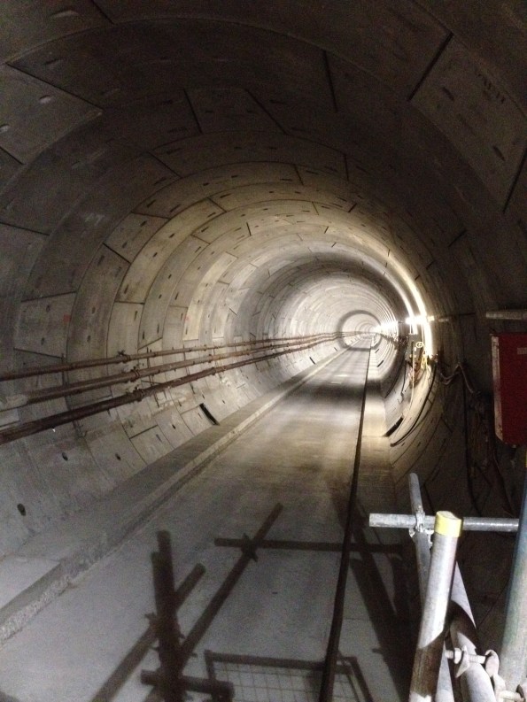
Figure 1. Another day in the office, looking East from Canary Wharf – the only station remotely on schedule. Note the absence of any building services!
C610 Team
The team consists of around 80 engineers, supply chain personnel and construction managers. The C610 contract and associated track power contracts total a third of the entire Crossrail budget (in the region of £350M over six years). In contrast to the other discrete station sites the C610 contract deals with the entire tunnel system (all 22 km) and needs to interface and deconflict with 14 separate stations and ventilation shafts; each with their own principle contractor. Standby for future blogs and TMRs regarding PC interface issues….
The C610 elements include:
– Tunnel ventilation.
– Tunnel drainage.
– Tunnel overhead lines.
– Tunnel fire and LV power installations.
– Temporary works during construction (e.g. temporary tunnel ventilation, construction power)
Paddington Station
I am part of the permanent tunnel ventilation team and have been designated the lead engineer responsible for the construction planning and installation of the equipment for Paddington station. I feel well prepared for this task as I once managed the build of a toilet block in Kenya. All tunnel ventilation systems are embedded within the station designs; requiring the M&E works to take place within another Prime Contractor’s’ jurisdiction.
The Paddington installation includes:
– 6 x 250 kW axial forced ventilation fans (each fan weighing 8.8 tonnes).
– Associated power-operated dampers, attenuators, transitions and ductwork.
– Variable speed drives, control system and SCADA interface.
– 11kV power supply.
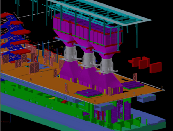
Figure 2. CAD Image of Paddington station with station box cut away. The fans are shown as silver cylinders with ducting transitions and dampers shown in purple; the blue stairwell at the left of the image gives a sense of scale.
The role will include managing suppliers, the site owners/prime contractors and installation sub-contractors as well as planning the logistics of the task in a congested London site. As construction actually starts at Paddington in Nov this year I will also be on-site working as part of a team of three engineers managing the installation of the identical ventilation equipment at Tottenham Court Road and Bond Street stations. Surprisingly I am the oldest member of the team at the tender age of 30! This work started last week, and will allow me to ‘tick-off’ a few more of the CEng competencies in the near future, as well as identifying all of the problems for ‘my’ station late in the year.
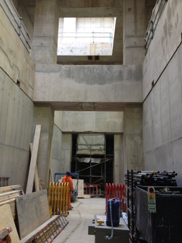
Figure 3. Fan halls waiting to be filled with shiny new M&E equipment; photo taken at ground level -3 floors. Not the tidiest site I have ever seen.
Otherwise, the attachment has started with a swift pace and no shortage of work to get my teeth into. Also, one of my team happens to be an Aussie – I welcome any cultural advice from my colleagues in the Southern hemisphere.
Regards,
Mark
Modules Anyone?
The project I am working on is making extensive use of pre-fabricated modules and so I thought it might be of interest to the other E&Ms. Here is a diagram showing the major module units that have been designed for the two buildings and tunnel being constructed as part of the project.
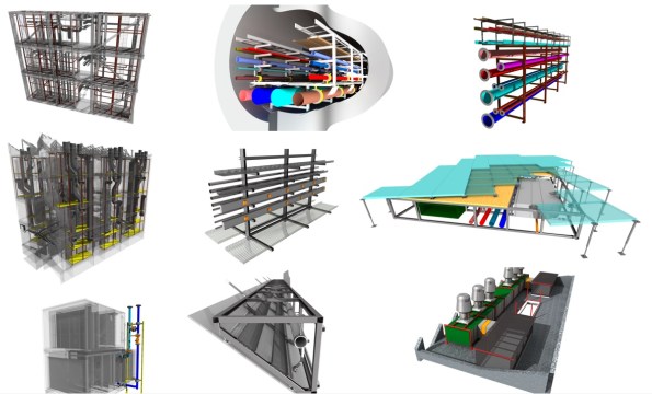
Figure 1 – BIM Model of 9 of the module units
Description
Top Left – Energy Centre Rises that connect to the tunnel modules
Top Centre – Tunnel Modules (3.5m Wide, 6m long and coupled together with a centre walkway)
Top Right – R&D Building Services Ring
Middle Left – R&D Risers (3 risers in total)
Middle Centre – Lab spine (medical gases, domestic services and 3 phase-busbars that can be tapped off anywhere in the labs)
Middle Right – Underfloor modules
Bottom Left – Cooling/heating Coils.
Bottom Centre – Sprinkler modules (600 of them concealed in the saw-tooth roof of the R&D centre)
Bottom Right – AHUs
Lab Spines
Of these modules, I think the lab spine modules may be of particular interest to the military engineer as recent operations have proven the necessity of rapidly deployable and easy to construct medical services. These modules would support this requirement very well and could provide a variety of services from medical gases and domestic services to power and data distribution.

Figure 2 – Showing the variety of medical services included
In order to install this spine system, each module is elevated and suspended from the ceiling and then the modules are braised together which also means that the level of craftsmanship required for installation is very low.

Figure 3 – The Lab Spine layout showing the tap-offs and outlets
This system is incredibly versatile and acts as a universal busbar where a tap-off can be placed anyway along the spine and the user can draw off 3-phase power, hot water, cold water, medical gases and compressed air.

Figure 4 – View of the medical gas outlets
In addition to providing services, the spine also acts as an open air cable tray, providing a tidy solution for internal wiring and data cabling.

Figure 5 – Electrical services are located at the rear with a busbar at the bottom and cable trays above
These modules are not due to be installed until April next year and so sadly I will not be involved in their installation and commissioning but I hope to be involved in the tendering and final specification as part of my phase two attachment.
The Devil is in the Detail
Phase 3A must construct three large temporary bridges that provide access through our site – both for adjacent phase’s construction traffic and future residents. The 3D CAD model below provides an illustration. I have responsibility for bridge 1. The bridge section spans over 54m and it has two decks of 24m length at either end. It will be suspended 18m above formation level (when we eventually dig down to basement 3 level).
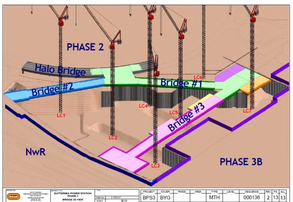 Temporary Bridge Structure – 3D CAD Model
The Problem
Bridge 1 must be in place to allow residential occupation of Phase 1 (Carillion’s site) in Q4 2016. As a result, the client’s driver is time. Unfortunately, the temporary bridges have been designed in isolation to the permanent structure and only considered on plan. As one can imagine this situation has created many clashes.
The Solution
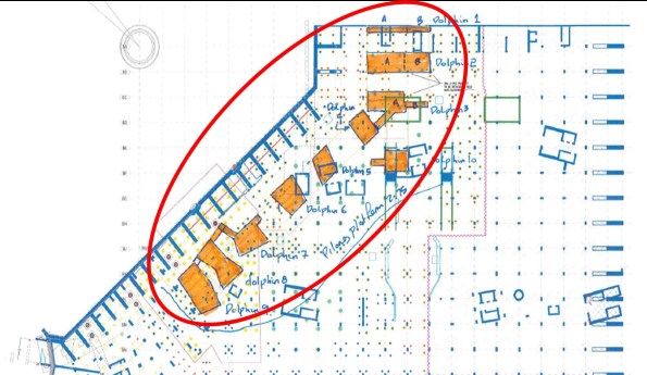
The Devil is in the detail and the solution requires all the stakeholders input. De-confliction is the name of the game and the majority of my time has been spent in meetings trying to work through solutions. The greatest difficulty lies in the area of the temporary bridge deck supports. These ‘dolphins’ (the nomenclature on the drawings) consist of piled foundations with high level pile caps that support the bridge deck. The drawing below illustrates the initial design with uniform spacing (coinciding with the deck spans).
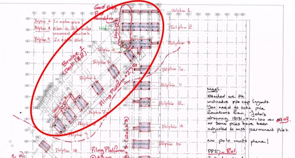 Bridge Supports – Initial Design (relatively uniform supports)
My task has been to knock heads together to come up with a mutually beneficial solution for all. I have convened meetings with the temporary bridge designers (McGee), the permanent structure designers (BuroHappold Engineering), the piling contractors (BBGE), the M&E designers (Chapman BDSP) and the construction sequencing team (Bouygues UK). The outcome of these painful liaison meetings can be seen below. One reason these meetings are so painful is because still no-one has signed a contract. Whilst not the most exciting Blog post the two photos represent a couple of weeks work and provide an idea of the small victories won. The next stage is to attempt to reduce the size of these temporary bridge supports…
 Bridge Supports – Post De-confliction (variable shaped supports)
Wasted work
In my last blog I mentioned that there had been a bit of a question 4 moment with regards to steam at LSHTM. This was based around the client asking me to explore other opportunities with regards to steam distribution.
In mid-March I took isometric drawings produced on Revit to the client for approval on the distribution strategy. Prior to conducting the work in Revit to produce these drawings I had discussed the proposed route with the Project Manager (PM) within the LSHTM estate’s team. The route I was proposing was based on taking steam from one side of the building where it was being generated at high level to where it was required on the other side of the building via an external route. This was because I had been briefed to minimise the amount of disruption to the building which would be fully operational during the works. I discussed this route with LSHTM’s PM and even took him to look at it with a possible contractor for comment on the buildability of my proposal. Having gained buy in of the client I proceeded to continue with the work and produce the required drawings in Revit, which took me approximately 1 week. What I failed to do was quickly mark-up a drawing by hand and send it to the client for them to approve formally. It was then at the meeting in March that a more senior member of the client team expressed disapproval with my proposal and asked me to look at another option. This is frustrating on a personal point of view as it is duplicating my work on the same experience and there is little competency experience to be gained from producing drawings in Revit (although being able to use Revit can go towards my A competency). It was also a missed opportunity from a BWL point of view. Because BWL are attempting to develop a relationship with LSHTM there was no resistance to LSHTM’s suggestion from my director. Probably in part because with me doing the work there is limited cost to BWL. If I had sent a mark-up which had been signed off by the client there is more chance that my time wouldn’t have been wasted in that the desire to explore other options could have been looked at prior to me doing the work in Revit, or if it had been approved I would have had an audit trail to fall back on. I could have more rigorously demonstrated that I had developed the design in good faith and that the proposal being made to consider another route was effectively a variation and required an additional fee. Whether my director would have wanted to do this is questionable, but it would have at least given BWL the option and has certainly taught me valuable lesson.
Design of Structural Elements Against Explosive Blast
I mentioned in my first blog that the construction of the ground floor slab is considered a critical milestone. With that for context you would assume that everything possible is being done to ensure the concrete pours on this slab are completed on programme. This brings me nicely on to the topic of this blog.
Early last week, only 60 mins before a significant concrete pour (50m³) was ready to begin on a key part of this slab, an issue was identified during final reinforcement inspections. This caused a fair amount of aggravation and stress on site between the consultant engineers and concrete package sub-contractors .
The issue relates to the column in Fig 1.1 and in particular the depth of fillet welds between the web and flanges. The column protrudes through the GF slab and was scheduled to be encased in concrete up to GF level as part of this pour. The engineer consultant, during his final check of the slab reinforcement bar, identified an issue with the welds on the column that stopped work until the senior structural engineers at the design office could be consulted.

Fig 1.1 – Incorrect Weld Configuration on Column L8
As I know the audience reading this blog adore explosives, and in particular blowing up military bridges on exercise, I thought they might be interested to hear that many of the structural elements have been designed to resist an explosive blast detonated at very close proximity.
Robustness in a building is usually achieved through one of a number of approaches. The most common is to design alternative load paths in case a structural element fails. On this project however, due to a late notice client dictated design change, this was not a viable approach. Robustness is therefore only provided through the alternative ‘protected element’ method. By this I mean key structural elements are designed with adequate individual robustness and additional protective measures (i.e. encased in sacrificial concrete or steel) to ensure they do not fail even when exposed to the designed worst case load condition.
In this particular column the weld design has been specified for this worst case condition. Unfortunately the column was not constructed in accordance with the design drawings. To provide suitable shear resistance in this element, the Blast Engineering Consultants specified a 70mm multi run fillet weld along the full length of the column to the base of the ground floor slab. As Fig 1.1 shows, the steel contractors only installed the fillet weld from the top of the column to the first web stiffener, leaving a considerable length of this column with minimal 15mm deep fillet welds. To try and understand the magnitude and context of the site engineers concern I tried to conduct some very basic analysis of this section.
In the first instance I modelled this problem as simply as possible and effectively considered the column as an I beam bending in one axis with an 8.6MN worst case vertical shear reaction force. To be clear from the outset, it will become apparent later in the blog that this model is far to simple for the complexities encountered in this problem.
Students on the civil stream will fondly remember the “Say It” equation which allows calculation of shear stress along a particular plane at any point in a bending beam. One of the key components in this formula is the thickness (b) of material providing longitudinal shear resistance along the assessed shear plane. The greater the (b) the smaller the shear stress. In steel plate sections a fillet weld exists to simply transfer the shear stresses from the flanges to the web so that the top and bottom flange can work together as a single beam (ie they know about each other). It’s worth noting that because these columns are steel plate girders, there is no monolithic connection between the web and flanges to provide an additional contribution towards this shear resistance. I have simplified the diagram to sum this up and illustrate why the reduction of this weld from 70mm to 15mm might be a problem.

Fig 1.2 – Simplified Column Section Model
Diagram A shows the steel column, as installed, below the web stiffener. Along this length the fillet weld installed is only 15mm in width each side of the web, this provides a total (b) of only 30mm. Diagram B shows the steel column where the fillet weld has been correctly installed. This weld, 70mm on each side of the web, provides a total (b) of 140mm of resistance along this shear plane.
In accordance with BSEN 93-1-8 Para 4.5.2 you actually need to use the effective Throat thickness (a) of each weld in this calculation (This provides a conservative estimate) which can be acquired with some simple trigonometry. I calculated weld throat values of 10.6mm and 49.5mm for case A and B respectively. These figures are then doubled through most of the calculations because we have a weld on both sides of the web.
I then plugged these dimensions and the known constants into the “Say It” equation, with the two different welds considered, to analyse the varying shear stresses induced as a result of the designed maximum blast load occurring on the column:
Calculation Details:
Max Vertical Shear Force on Section Vz = 8.6 MN
Second Moment of Area = 32.77 x 10⁴ mm⁴
Distance from NA to Centroid of Area above shear plane = 200mm
Area above Shear Plane = 38400mm²
Width of Material under shear (Weld Throat): Case A = 21.2mm
Width of Material under shear (Weld Throat) : Case B = 99mm
After I’d run the calcs through using the information above I got the following shear stress values through the welds in each case:
Shear Stress in Weld:
Case A: 950.7 N/mm²
Case B: 203.6 N/mm²
I also calculated the greatest shear stress likely to be seen in the I section for both examples in order to allow further comparison. We know this appears along the NA where the web in this case is 60mm. I ended up with shear stress values as below.
Shear Stress along NA – Web:
Case A: 371.1 N/mm²
Case B: 398.78 N/mm²
When you look at this logically, it raises a few interesting points. In Case A the shear stress expected in the weld is over 2.5 x greater than that seen in the web on the NA. Therefore, when affected by the blast load, the weld is likely to fail long before the web of this section.
In Case B however the weld sees an expected stress that is approximately half the shear stress seen along the NA in the web. In this case it is likely the web would fail before the weld. This suggests the 70mm weld is therefore larger than actually required. Generally a design throat thickness of an I section, doubled to account for both sides of the weld, should be a similar depth as the web thickness on that section. Any additional weld depth is most often unnecessary because the failure risk is transferred to the web.
Using BSEN I then checked the actual permissible shear stress in each weld. In both cases I calculated this to be 230.9 N/mm². When you compare this to the expected stresses, it is clear that the fillet weld in case B is capable of carrying the design stress of 203.6 N/mm² but not the 950 N/mm² of case A; clear indication that the 15mm weld is grossly under strength for the worst case load condition assumed in this model.
I mentioned that my first model kept this analysis as simple as possible. In reality the problem is considerably more complex for a number of reasons. Firstly, I assumed the blast occurred directly perpendicular to top flange. Blasts occurring at different angles to the section would undoubtedly affect the results. In addition to the 8.6MN vertical shear reaction load I considered on the section there is also a 9.5MN axial load from the weight of the building applying a compressive pre stress through the column. Furthermore, the complex nature of the dynamic/impulsive blast load on the section is also far more challenging to categorise; it is affected by numerous variables including charge size and type, stand off, ambient pressure and charge proximity to the ground, amongst others. The response of a steel column to a blast load is also influenced by stiffness, its dimensions, vibration period and strain-rate. The point being, this is far too complex to analyse with such a simple model.
What is very clear is that no one in the project team seems to understand the science or engineering behind the blast design analysis. All we know is that there is a specified design explosion and the consultants tell us the size of elements required to provide robustness. If I can learn about the science and engineering models applied in the space and time between the immediate explosion and its impact on the column I will probably know more than most of my immediate colleagues and have a potentially interesting thesis topic. Fortunately I have managed to arrange a visit to the blast design consultants test facility in the coming weeks to see first hand how they model their problems to produce the design output. With any luck they will also let me blow up some steel columns in the name of thesis or TMR research.
In practical management terms the project team on site got irritated by this problem because the column had been in position for three weeks before the issue was spotted. Had we employed more thorough quality assurance inspections, it is likely this issue would have been picked up earlier.
This incident is also a potential indication of a more commonplace issue. From a brief investigation I am certain that the column was inspected and signed off imediately after installation. The likely problem therefore, I’m speculating only, is that the individual who inspected and signed off the steel either didn’t do it thoroughly, made a mistake or potentially didn’t know the detail of what they were looking for when completing this process. Which raises the question of how to best ensure QA inspections of completed work are only conducted by individuals capable of understanding the technical importance of the details contained on drawings and specifications.
Once I have got more information on the modelling methods used by the blast consultants I will attempt to publish another blog on the subject and its affect on my own analysis of the issue identified.
Silver Spoon, Wooden Spoon
My design attachment has been very different from what I expected (I blogged about this a few weeks ago).
It seemed as though I had been given the silver spoon with the design manager job for the Calder Highway Overtaking Lanes (CHOTL). It doesn’t give me quite as much depth as I was hoping for, but the breadth is there in terms of attribute achievement. But it would seem that with my silver came a wooden one too…
I don’t have much else to focus on in the office (anything, in fact). Managing the CHOTL project has busy days and quiet days. As a Contractor seconded to GHD, I have to fill in a weekly timesheet that charges to whatever job I am working on. I was ‘sold’ to GHD by JHG, promising 40 hours per week for them to do with me what they will.
The issue I raised this end yesterday is that I am here until the middle/end of June. The estimate for the CHOTL project only allows 150 hours of my time (3.5 weeks full time). So the more time I invest in my project (or charge to it, at least), the greater my chance of going over budget. If I clock in fewer hours then GHD is ‘not getting their money’s worth’. Seems a little short sighted sticking me on a modest lump-sum agreement project with a 12 week timeline and when I can only apply myself for a third of it.
If I was GHD, I would be frantically trying to find a bigger project with a bigger Client to charge me to.
