Archive
Crossrail Tunnel Ventilation Team
My feet are now well beneath the desk and am getting stuck in with my attachment within the Alstom, TSO and Costain joint venture (ATCjv) working on the Crossrail tunnel M&E fit-out contract (contract number 610, shortened to C610). The aim of this blog is to briefly outline the role of my team and my tasks over the Phase 2 placement.
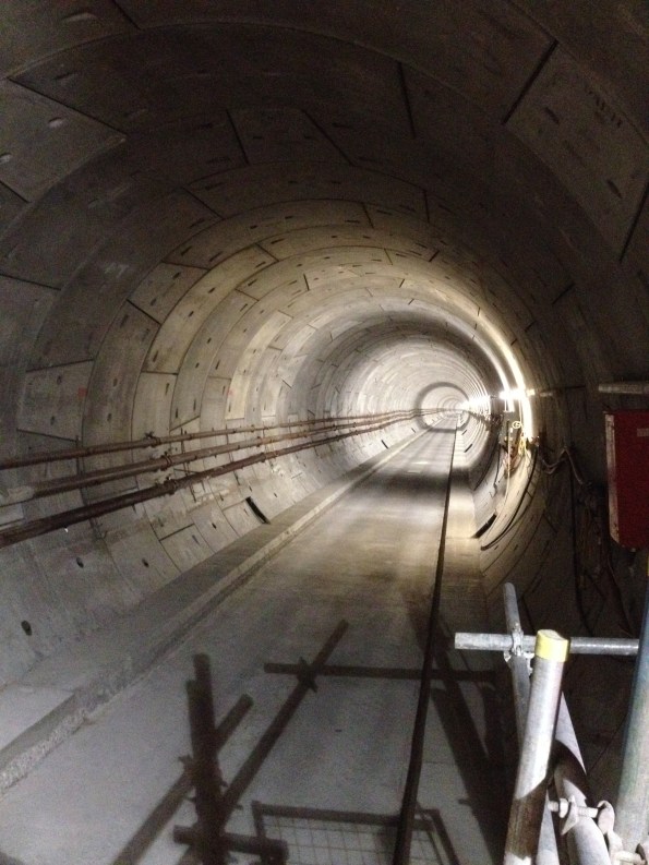
Figure 1. Another day in the office, looking East from Canary Wharf – the only station remotely on schedule. Note the absence of any building services!
C610 Team
The team consists of around 80 engineers, supply chain personnel and construction managers. The C610 contract and associated track power contracts total a third of the entire Crossrail budget (in the region of £350M over six years). In contrast to the other discrete station sites the C610 contract deals with the entire tunnel system (all 22 km) and needs to interface and deconflict with 14 separate stations and ventilation shafts; each with their own principle contractor. Standby for future blogs and TMRs regarding PC interface issues….
The C610 elements include:
– Tunnel ventilation.
– Tunnel drainage.
– Tunnel overhead lines.
– Tunnel fire and LV power installations.
– Temporary works during construction (e.g. temporary tunnel ventilation, construction power)
Paddington Station
I am part of the permanent tunnel ventilation team and have been designated the lead engineer responsible for the construction planning and installation of the equipment for Paddington station. I feel well prepared for this task as I once managed the build of a toilet block in Kenya. All tunnel ventilation systems are embedded within the station designs; requiring the M&E works to take place within another Prime Contractor’s’ jurisdiction.
The Paddington installation includes:
– 6 x 250 kW axial forced ventilation fans (each fan weighing 8.8 tonnes).
– Associated power-operated dampers, attenuators, transitions and ductwork.
– Variable speed drives, control system and SCADA interface.
– 11kV power supply.
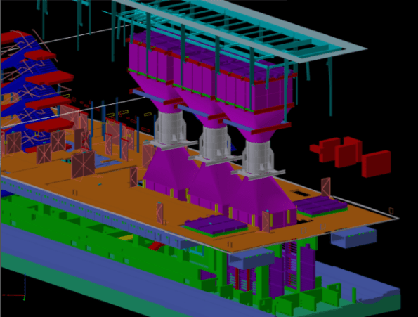
Figure 2. CAD Image of Paddington station with station box cut away. The fans are shown as silver cylinders with ducting transitions and dampers shown in purple; the blue stairwell at the left of the image gives a sense of scale.
The role will include managing suppliers, the site owners/prime contractors and installation sub-contractors as well as planning the logistics of the task in a congested London site. As construction actually starts at Paddington in Nov this year I will also be on-site working as part of a team of three engineers managing the installation of the identical ventilation equipment at Tottenham Court Road and Bond Street stations. Surprisingly I am the oldest member of the team at the tender age of 30! This work started last week, and will allow me to ‘tick-off’ a few more of the CEng competencies in the near future, as well as identifying all of the problems for ‘my’ station late in the year.
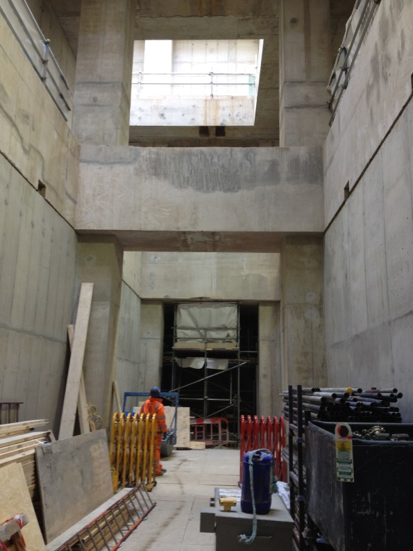
Figure 3. Fan halls waiting to be filled with shiny new M&E equipment; photo taken at ground level -3 floors. Not the tidiest site I have ever seen.
Otherwise, the attachment has started with a swift pace and no shortage of work to get my teeth into. Also, one of my team happens to be an Aussie – I welcome any cultural advice from my colleagues in the Southern hemisphere.
Regards,
Mark
Modules Anyone?
The project I am working on is making extensive use of pre-fabricated modules and so I thought it might be of interest to the other E&Ms. Here is a diagram showing the major module units that have been designed for the two buildings and tunnel being constructed as part of the project.
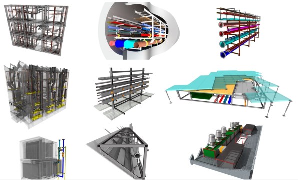
Figure 1 – BIM Model of 9 of the module units
Description
Top Left – Energy Centre Rises that connect to the tunnel modules
Top Centre – Tunnel Modules (3.5m Wide, 6m long and coupled together with a centre walkway)
Top Right – R&D Building Services Ring
Middle Left – R&D Risers (3 risers in total)
Middle Centre – Lab spine (medical gases, domestic services and 3 phase-busbars that can be tapped off anywhere in the labs)
Middle Right – Underfloor modules
Bottom Left – Cooling/heating Coils.
Bottom Centre – Sprinkler modules (600 of them concealed in the saw-tooth roof of the R&D centre)
Bottom Right – AHUs
Lab Spines
Of these modules, I think the lab spine modules may be of particular interest to the military engineer as recent operations have proven the necessity of rapidly deployable and easy to construct medical services. These modules would support this requirement very well and could provide a variety of services from medical gases and domestic services to power and data distribution.

Figure 2 – Showing the variety of medical services included
In order to install this spine system, each module is elevated and suspended from the ceiling and then the modules are braised together which also means that the level of craftsmanship required for installation is very low.

Figure 3 – The Lab Spine layout showing the tap-offs and outlets
This system is incredibly versatile and acts as a universal busbar where a tap-off can be placed anyway along the spine and the user can draw off 3-phase power, hot water, cold water, medical gases and compressed air.

Figure 4 – View of the medical gas outlets
In addition to providing services, the spine also acts as an open air cable tray, providing a tidy solution for internal wiring and data cabling.

Figure 5 – Electrical services are located at the rear with a busbar at the bottom and cable trays above
These modules are not due to be installed until April next year and so sadly I will not be involved in their installation and commissioning but I hope to be involved in the tendering and final specification as part of my phase two attachment.
