Archive
Bored piles – analysis of issues and recommendations
As promised in a previous blog, see below for a synopsis of the key risks, issues and recommendations from the piling on Australia 108
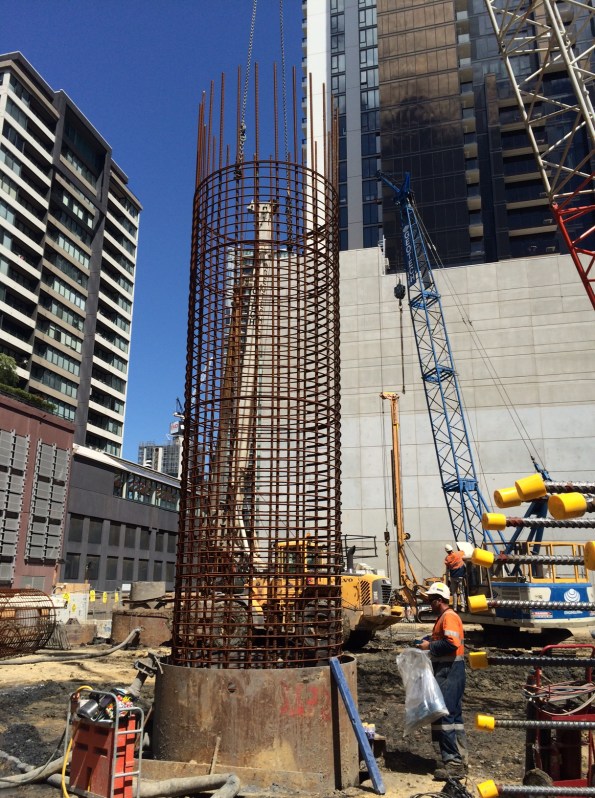
Analysis of issues encountered with bored piles
The delivery of deep foundations on any large project is always on the critical path. The risks inherent to piling are substantial and failure to identify and mitigate these risks adequately can lead to significant impact on cost, schedule and performance of the piles. Both the client and contractor have a vested interest to develop and implement an effective risk mitigation strategy to avoid such risks from being realised. The recurring nature of some of the key issues during piling on Australia 108 signifies they did not occur by misfortune indicating that risk could have been managed better, and some issues avoided.
There are two primary requirements associated with piles: piled foundations must have both the structural capacity and geotechnical bearing capacity to safely transfer the actions from the superstructure to the ground without requiring excessive strain to develop the load capacity.
Risk and mitigation
Risks associated with piling are generally accepted as fitting four categories:
- Risk of encountering unexpected ground conditions.
- Risk to foundation performance.
- Risk to construction productivity.
- Risk of construction defects.
Mitigation strategies generally adopted:
- Geotechnical Design Report. Identification of risk and recommended design solution. Any residual risk should be identified to ensure it can be mitigated through construction processes.
- Risk Transfer. Design-Construct contracts transfers some risk to the subcontractor. Costs can always be passed to the subcontractor if they fail to mitigate risk appropriately, however time cannot be recouped once lost due to delay. The attempt to reduce the overall project delay applies early pressure to a program which will often risk compromising quality.
- Testing pile performance. This verifies that piles have reached their design performance criteria. Increasing the rate and reliability of testing procedures affords greater design resistance to the piles, increasing the redundancy they offer for the same design effect.
- Construction methodology. This must be simple and specific to mitigate residual risk from design by avoiding any ambiguity or interpretation in construction procedures.
- Technical competence. The most effective way to mitigate risk is being able to recognise early that a risk is materialising as an issue. A timely, informed decision on appropriate action to mitigate that risk, balancing time and cost, is essential to limit the impact of that risk.
The underlying causes of materialised risk are often:
- Failure to identify the risk.
- Failure to recognise the risk was becoming an issues.
- The risk was identified but inappropriately evaluated.
- The was identified but due to either time or cost incentives, risk mitigation was not applied.
Australia 108
Foreseeable risks on Australia 108
- Difficulty drilling through the basalt in the Northern sector.
- Settlement of Coode Island Silt (clay) relative to the piles creating negative skin friction.
- Necking of the boreholes due to the soft clay collapsing and loss/contamination of polymer support fluid with ground water through gravel layers.
- Ability to core for establishment of pile in siltstone.
- Structural capacity of the pile due to high axial loads and eccentricities.
Issues encountered on Australia 108
- Out of position piles. 35% of 48 bored piles were out of position by more than the tolerance leading to significant rectification measures and redesign.
- Reduced drilling rates through basalt. The basalt encountered was harder and thicker than anticipated significantly slowing progress.
- Voided pile. The voided pile was due to broken equipment abandoned in the borehole while drilling through basalt. This resulted in additional piles being drilled either side and significantly increasing ground works to gain access.
- Borehole collapse. Either identified during drilling which required additional drilling to correct; or during the concrete pour which risked the performance of the piles and additional testing was required to verify the pile.
- Excessive sediments. Encountered in the base of piles and required significant airlifting prior to pouring, sometimes resulting in concrete pour being delayed a day due to the remaining time on site being insufficient to pour.
- Pile cages placed too low. Cages installed at incorrect RLs required additional breaking back of piles in 80MPa concrete to locate cage followed by rectification of pile and additional welded bar to ensure correct development length of starter bars.
Recommendations
- Identify the high risk piles using probability vs impact of risk materialising. This will focus QA efforts on the right piles.
- Be specific in the construction methodology about techniques to be used to reduce any ambiguity. Ensure it is followed on site. Measures in the construction methodology are there to mitigate risk.
- Check location of casing of bored piles after drilling before pouring. Out of tolerance piles can be evaluated prior to pouring. Redrilling of the pile now may have less impact on the program than rectification measures to the structure later. (This might be implemented for the piles identified as high risk).
- Use of GPS in the drilling rig will give real-time information on location, depth and verticality of the borehole allowing early identification of casing shift.
- Appropriate identification and classification of soils strata, specifically rock with regard to location and strength. On Australia 108, the basalt was not included in the design stratigraphy for the piles.
- If using polymer, slow and steady extraction rates of the drill reduces the likelihood of suction on the boreholes, reducing the effectiveness of the polymer chains used to support the borehole. If collapse is occurring in soft soils, slow the drilling and extraction rate down.
- Keep polymer levels 1-2m above the ground water level to reduce the risk of borehole collapse.
- Good polymer management is key to reducing the sediment within the polymer; especially prevalent when recycling the polymer from one borehole to another. Reducing the sediment pumped into the boreholes, reduces the need to pump out prior to pouring.
- Good polymer management is key to ensuring the polymer chains are effective. Check the length of the polymer chains dripping from the drill on extraction. Long chains indicate an effective polymer. Shorter chains indicate that new polymer needs to be mixed in.
- Requirement to check the RL of the pile cage prior to pouring. If necessary, the pile cages can be built up above the level of the polymer to check; or the length and laps of the cages be checked and recorded prior to installation.
Vertically Challenged
My scope of works in delivering the detailed design of two overtaking lanes (OTLs) in the middle of nowhere included identifying any show stoppers during a site walkover survey, which I did – twice.
Now that the design is well and truly underway, we have found that the vertical alignment does not meet the Austroads sight safety distances. So what? Well the Client stated the OTLs are to tie into the existing pavement which implies the vertical alignment is okay. Should I have identified this show-stopper? Impossible without a $20k survey.
What now? I rang the Client and told them what we had discovered. But they pay us for solutions, not problems. Understandably, they weren’t too chuffed with my solutions:
- Reduce the speed limit on the OTL to 80km/h. Yup. Genuine option.
- Regrade the zones to meet the safety standards. $$$$.
How could this happen? Well, the highway was built decades before the standards were published. Effectively, most of the highways in AUS could be sub-standard.
In my opinion, the Client is going to have to re-grade, or just accept the risk that someone might not see a 20cm high bunny rabbit from 210m away and just run it over. Easter is over-rated anyway.

We will rock you
So in my last post I said I would cover a little about working with rock. I am currently excavating in low to medium strength phyllite. Phyllite is a metamorphic mudstone somewhere between slate and schist. It is highly foliated and has fine clay like material in between the layers. The foliation is at 70 degrees to the horizontal across the site. Despite being fairly weathered it is still relatively intact with only a few faults across the site. RQD was between 50-75 % across site. The problem is it weathers so incredibly quickly when wet. I am about 15 m below the water table and water coming through the anchors at about 5 litres per minute. So what I hear you cry – well its rock but it is a galactic pain in the back side to work with.
I am now down at footing level and I am faced with an even worse problem than the bulk excavation. The design has called for individual pad footings which are all at different levels and a core that is 3 m below any of the other pad footings. There are zone of influence clashes everywhere, the architect/structural engineers have very helpfully not included any footing RL so I have had to work them out, as well as how we are going to get the batters and benches in while still being able to move. The geotechnical report states that with low strength phyillite I can achieve a batter of 0.7 H and meduim strength 0.5 H. With H being the height of the batter (not exceeding 3m). So rock strength can be pretty important.Footings Handover Schedule
What strength is that rock? You cannot just take the results of the lab test for Ultimate compressive strength and point load tests. There is a very good website that helps with estimating rock strength via the Rock Mass Rating (RMR) process (RMR rating)that can be then used to calculate the allowable/safe bearing pressure for foundation design. Ultimately though this counts for very little as to get anything signed off you end up with a geotech going mental with a geo hammer on site before telling you its half of the strength you have calculated.
A conversation with the local geotech went along the lines of “how do you come up with the safe bearing pressure do you use RMR.”
“RMR what’s that? Nah, I just use experience, umm what does the drawings say this should be?”
Incidentally I got an RMR of around 45 -50 across the site. That gives between 2880- 1510 KPa am I right?

I made the mistake of being over confident with the bench and ended up having get the geotech back in. In my defence I excavated a pad footing expecting it to be open for the maximum of a week and the PM didn’t make the call on the steel contractors in time so it was open for nearly 3 weeks. The result was water got in and the sides blew out, I had to get the geotech and subbies back in to batter back a ridiculous amount. This all meant time, concrete and money.
There is worse to come – the other Site engineer (little e deliberate)- to be now known as ‘the lone ranger’ took responsibility for the crane base and has massively ‘dropped his baseball’. He wrongly measured the zone of influence of the crane base to the core and failed to gain approval for the design of the pad footing from the geotechs. We are now faced with delaying the tower crane erection or digging the pad footing deeper. It hopefully won’t end up like the crane around the corner though, which has a lovely lean to it. 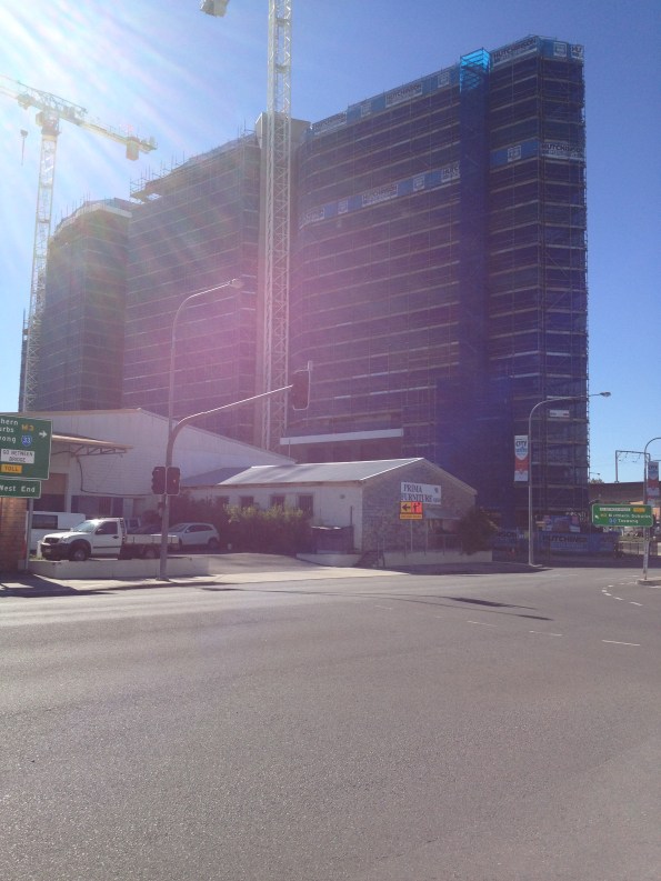
Prima furniture may be getting some renovation work done in the future.
Calling all aspiring structural engineers
Evening all,
A short and sweet post. As a lowly E&M engineer in training I am interested in some second opinions on the deflection of steel structures under load.
This week I have been occupied with installing temporary tunnel ventilation fans in the -5 level of Bond Street Station. The fans weigh around 3500kgs and will be in operation for around 18 months. The first of four fans was due to be moved into place today using a porta-gantry onto a simple steel frame.
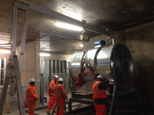
The fan being lowered into position on the support frame
Upon lowering the fan onto the support one of the operatives spotted a part of the frame deflecting under the applied load. The web of a channel section was bending inwards as the chain hoist lowered the fan, distorting the anti-vibration mounts.
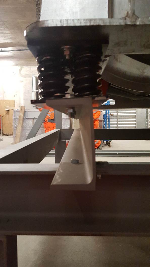
Apologies for the poor photo. If you draw a line along the top and bottom flanges of the C-section they are no longer parallel; causing distortion to the anti-vibration mounts. The lift was stopped before the full load was applied.
This would all be highly interesting except for the fact that I am only SMSTS qualified person on site and conducted the brief for the works. It also came down to me and a grad mechanical engineer to judge whether the deflection the channel was showing was acceptable, and whether to continue lowering the full load onto the deflecting frame. After some teeth sucking and discussion with the lift AP we decided to lift it back off and question the frame designers. Queue a lot of Northern blokes pissed off that they had wasted a days’ work. Reminds me of being a Troop Commander.
On removing the load the channel returned to its original shape with no permanent deformation.
Was it the right decision to stop the lift? Or can you expect visible deformation on a channel loaded in this direction? Is this the right steel section to use for this application?
Risk-based Cost Estimating
One of my recommendations in an early AER was that the APM method (bottom-up) of estimating was useable and effective in forecasting my budgets. Another was that line items in a risk register should not be expected to occur in isolation – they often work in alliance e.g. groundwater slowing shaft excavation and affecting tunnelling rate (critical path). Three separate cost codes which were all affected by one item. In my next breath I am going to retract my first recommendation and offer you risk-based cost estimating.
My job in design is a small one worth less than my annual salary, but there have been a few golden nuggets to take away. One of my deliverables in the detailed design for a highway widening scheme is an estimate on what the works are likely to cost, using the Client’s risk-based cost estimate template. It is essentially a Monte-Carlo analysis (M-C).
Similar to the RMS (Root Mean Square) method, the M-C identifies that the likelihood of all maximum risk values occurring on one project is low. Using data which the user inputs, it models thousands of possible scenarios (or risks) on a project occurring to greater and lesser degrees.
I modelled a simple fantasy project with the same worst, most likely and best case costs using the PERT analysis, and compared the results with the M-C. The end product is a normal distribution curve (screenshot below) which gives you the likelihood or confidence (%) of the project costing ‘X’ (£).
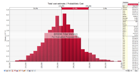
The PERT results gave me a 50% chance that the project would cost $232k, and a 95% chance that it would cost $268k.
The M-C 50% result was also $232k, but I could be 95% sure it could be done for $249k.
So what? As a Client with numerous projects in a programme, you’d be better informed on where to put your money.
I’ve now used bottom-up estimating, PERT, RMS and M-C. All have their pros and cons but the RMS and M-C must be considered the better options. I would argue that unless you have the M-C software package, or Damo to build one on excel, the RMS is sufficient. Both share the same limitation in that they inevitably spit out numbers based on subjective information – garbage in is garbage out. There lies the risk within the risk analysis.
London Skyline
Introduction
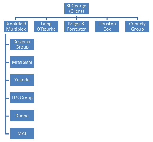
After a few weeks working on site and a trip to Borneo it is time for a blog. I’m currently working for Brookfield Multiplex (BM) on One Blackfriars Road (OBR) in central London. BM specialises in constructing high rise buildings or in their own corporate words “We build skylines London/Dubai/Sydney…”.


Overview
BM are constructing a 50 storey residential tower to shell and core status, hotel including fit out and a 4 storey retail podium including all the Mechanical Electrical and Public Health (MEP). Below the entire site is a 3 storey basement which contains all the centralised building services, hotel swimming pool and some very expensive parking spaces.
Shell and Core Status
Shell and core for the tower comprises of the structure, façade, common areas, external works and base plant.
The base plant is mostly M&E and includes:-
- High and low voltage switchgear.
- Transformers.
- Lift systems.
- A standby generator.
- Boilers.
- Chillers.
- Cooling towers.
- Water and fuel tanks.
- Sprinkler plant.
- Building control systems.
- Air conditioning chambers and fans.
- Water and fuel pumps.
- Dry risers.
- Fire detection, alarm and hose reel systems.
The Client
The client is St George part of the Berkley Group and they are a very ‘hands on’ client with their own project management team on site to manage their own sub-contractors and BM (Principal Contractor). All communication for St George’s subcontractors has to go via the client, which makes it slightly more difficult for BM to effectively manage the entire site. St George are heavily involved with significant developments requiring approval such as jumping the crane, site access and storage, and changing over the power supply from one substation to another.
Role
I have been given the role of Assistant MEP Site Manage and are responsible for managing the installation of the following systems within the Tower and Basement:-
- Condenser system.
- Domestic water.
- Wet riser system.
- Low temperature hot water.
- Low voltage power distribution.
- Heating, ventilating and air-conditioning system.
- Combined heat power.
- Lift systems.
Sectional Handover
The Tower is broken down into sections of 2 to 3 floors and a new section is handed over to the Client almost every 3 weeks. Therefore I’ve been heavily involved with managing the installation and the MEP handover for Section 2&3.
BM have handed over Sections 1-3 and are currently working on Section 4 but the Client has failed to accept any of Sections and it places the liquidated and ascertained damages for the 3 Sections at circa £105k per day. The main issue is the façade and the Client is refusing to inspect the outer façade because they believe it to be dirty and then they have refused to inspect the inside façade because of the outer. Still to be resolved.
View from Level 25
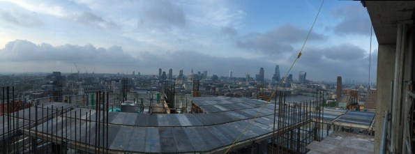
The 5 storey penthouse is still for sale…
Regards
Alex
Trouble At Mill
Trouble at Mill
So it has been a while since I have contributed anything. I have been placed I charge of the bulk excavation and installation of rock anchors. Brisbane Casino Towers is now down to Bulk Excavation Level across half of the site and I am supervising the detailed excavation before handing over to the Structural Site ‘engineer’ (the lack of capitals is deliberate). The last 2 months have been somewhat of a rollercoaster and I have learned a great deal from the experience. With the approach of AER 2 it is a good point to review some of the issues that I have had overcome.
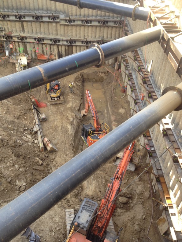
Loading Platform
In order to assist with the extraction of soil from the site a loading platform was designed to carry a 47 Tonne excavator. The loading platform was situated on the Hope Street side of the excavation. On 14 April 2016, the braces on the loading platform buckled, halting all loading out of soil and stopping all construction materials from being loaded in. There was a two day delay while engineers could assess the problem and carry out repair work.
The braces buckled due to movement in the secant pile wall that induced a load that exceeded the capacity of the I wrote a TMR on the buckled braces and the stability of the platform down to foundation level. It turns out that at full excavation the wall movement could cause failure and I recommended some alternate tension only restraints back to the secant pile wall as well as a brace back to the loading platform deck to limit the effective length. We held a conference with the designers who were reluctant to admit any wrong doing and just wanted to replace the braces like for like. My PM’s decsion was that we had the sign off from a qualified engineer so it wasnt a problem!
Thankfully the 47 T excavator has now gone and a long reach (33T) has replaced it. The sub-contractor has decide not to risk it (I may have had a word in his ear) so is leaving the excavation high underneath the platform until the platform is removed which has therefore limited the deflection of the retaining wall and the effective length of the plunge columns.
Wallap Analysis. Caution should be used in future projects in the extent to which Wallap analysis can be relied upon for predicting deformations. A safe approach to take is to assume that a wall will deform and design accordingly. Future deformations should be quoted within a range (for example 25-50 mm) to give the appropriate level of understanding to those unfamiliar with geotechnical analysis.
Safety. The Australian approach to safety is similar to the UK’s but different. The Union are seen as the gatekeepers of safety and not the government. Occupational Health and Safety are Australia’s version of version of HSE but they don’t have anything like the powers. Instead Union delegates hold builders to ransom over safety and the approach can seem sporadic at best. BM have a minimal approach to PPE and it is not unusual to see guys laying concrete in board shorts.
 If provoked will strike!
Industrial Relations. Seemingly minor issues are over inflated to put pressure on the state and national governments or employers. The Union effects almost everything in the construction industry and sub-contractors can be blackballed and banned from site even if they have gone through a comprehensive tender process. Walk-outs are common and safety/welfare incidents can be orchestrated to give the pretence for a walk out. To make matters worse if workers down tool for safety reasons they are entitled to a full day’s pay and can even be paid to leave site for a 2hr meeting/march. My site is only around the corner from the Union Headquarters so workers are typically called in for rent a mob demonstrations. It is so bad that you cannot even use the word ‘union’ in correspondence. I had a walk out on site relating to cracks in the secant pile wall when I was drilling the first row of ground anchors. Despite displaying the monitoring results and analysis of the wall the Union delegate held the company over a barrel making various demands before allowing the boys back to work. As a consequence our survey budget has been blown out of the water monitoring wall deflections daily. The only consolation I have is that as bad as they are here they are even worse in Melbourne – you have my sympathy Jo.
![IMG_2697[1]](https://pewpetblog.com/wp-content/uploads/2016/05/img_26971.jpg?w=351&h=468)
First footing in and boom the steel budget gone
Budget. Money is really to tight to mention on this job. BM bought the work from the client in the hope of becoming the preferred contractor. As such we are trying to cut costs all over the place. The decision has been made not to pour blinder and we are laying the footing straight onto the phyllite rock. Incredibly BM have run out of money for steel after our first footing. At tender the consulting engineer estimated 50 Kg/m3 as opposed to the 80-100 Kg/m3. We have blown that in the first mammoth pad footing. Another Brisbane Casino Towers budgeting classic. We are debating the merits of back charging the consultant as we speak.
Pile Tolerance. The secant pile wall is the permanent solution for the retaining wall. At a depth 18 m the worst offending piles are off by approximately 200 mm and need to be ‘scabbled’ back in order to fit the ground anchor walers on. This causes an issue as the cover is supposed to be only 150 mm, so far we have not hit steel and I am beginning to wonder if they are reinforced! The piling contractor (Franki) actually haven’t done a bad job as out of the 264 piles on the job only 8 are problem children. I have been told by the Franki that you would be unlikely to see this type of wall beyond 6 m in depth in Europe.
Programme. We are currently 10 days behind programme and Delta are due to pay $15,000 a day for every day they delay the basement handover. So this could be quite expensive for them. BM are less interested in pursuing the Liquidated Damages (LD) are more interested in getting the time back as BM’s LDs to the client for delayed completion are nearly 3 times that. So why did these companies agree to the LDs, well they are part of how business gets done down under and are routinely incorporated into every contract. Normally the LDs are not pursued because there is a small construction community but given the tight budget that BM are operating under they have very little choice.
I have probably written enough for one post but I will follow up with another article on rock anchors and engineering in rock.
Rich/Dam0
PSB![IMG_2714[1]](https://pewpetblog.com/wp-content/uploads/2016/05/img_27141.jpg?w=595)
Calcs are indicative only!! (The brace is 6 m long)
A WHEEL WASH – YES HONESTLY THE STORY OF A WHEEL WASH
Occasionally, I read others blogs and I despair – I am not dealing with safety critical testing, I have not touched out of tolerance piles and certainly not experienced the delights of BIM. Instead I have been busy dealing with the position of a wheel wash… That is correct, the complexities of where to place a giant car wash on steroids. As an aside, the site right next door doesn’t need a wheel wash as NLE use a conveyor and barges to dispose of their spoil. In the process they stockpile all their muck right next to our temporary sheet piles creating surcharge loading that no-one has considered. However, that story is for another blog.
The Problem
Approximately 120 muck away tippers per day, scheduled to increase, when Phase 3 start to excavate the basement levels. A shared access route – Phase 1 (Carillion), Phase 2 (Skanska) and Barhale are all on site (as principal contractors). To further compound the congestion Thames Tideway preparatory works have closed one of the public access roads. Finally, the location of the wheel wash must not clash with permanent structure works. The sketch below shows the access route highlighted in red with the locations of the different Phases and the permanent bearing piles, temporary sheet piles, and permanent secant pile walls.
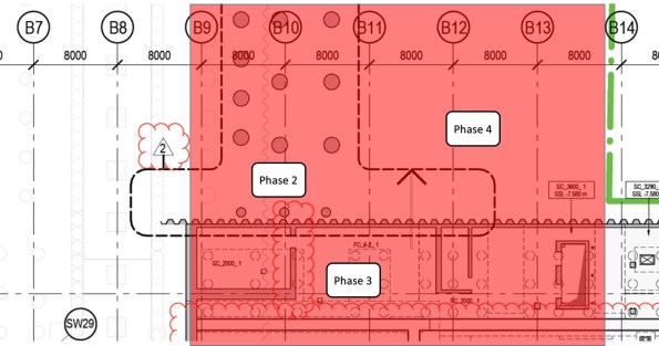
Phase 3 Entrance – Showing the permanent pile locations (red shading access route)
The Solution
My previous blog discussed the requirement for collating detail from all stakeholders. Well, nothing has changed and once again a great deal of my time has been spent arranging meetings. This time it has concerned the interface with the other phases. I have spent numerous hours with McGee (Phase 3 ground works contractor), Bouygues UK methods team (from a construction phasing perspective), Skanska (Phase 2 Principle Contractor), Blu 3 (Phase 2/client’s ground work contractor), Keltbray (Phase 2 sheet piling contractor), Clipfine (BPS site wide logistics and security) and frankly a host of muppets from the clients side… The solution is shown below and as one can imagine this is not an intellectually challenging issue, nor is the solution technically difficult – the draining aspect of this managerial issue is dealing with a group of people who appear incapable of making a decision. It highlights the difficulties of project management on a multi-phased development and is potentially my next TMR.
I am sure you will all have thought of the solution – A single wheel wash directly procured by the client for all Phases but why this has not been done; only the muppets that I mentioned above can confirm!
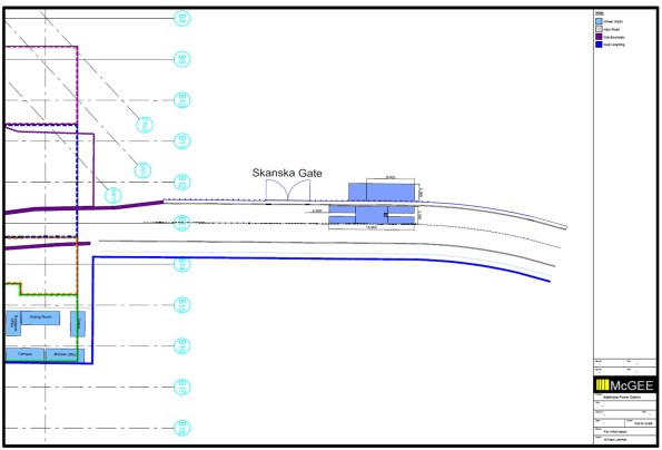 Phase 3 Wheel Wash Location – in the final agreed position (hopefully)
A problem with BIM
Following on the BIM theme from Rich, I thought I’d share a new concern that has arisen in my office.
I work for the Ports and Martine Division at CH2M, one of two global specialist in large container terminals and large port infrastructure. The benefit of being a huge fish in a small client pool is you pretty much win the jobs you want, over price the jobs you don’t want to make big profit or, if you’re busy developers (sometimes) wait until you have capacity. It also means that you’re able to constantly refine what you’re doing and when a new player appears, you can price them out of the game!
There is a weakness in this armor however…….BIM!!!!
The tender team have received a job brief to prepare a bid for a new container port on the Panama Canal. The tender pack contained some BIM images and design of concepts ideas used to win planning authority for the job. The client (a global shipping company) used a US consultant to support planning approval and to help prepare the tender brief. The problem is that the tender brief contains 3D designs and models produced by my office for another job, for the same client, in the Middle East.
So…anyone that has received that tender brief has CH2Ms design, 3D CAD protocols and material information attributed to the model. Luckily in this case the design assumptions weren’t included as it was an early BIM’d project but who knows what will appear next time. Realistically, it’s now just a matter of time until other companies learn enough from the established players to challenge the market.
We (the military) talk about the security concerns associated with BIM but commercially, money is security. At the moment no one quite knows how to address it but the initial thoughts include strengthen contracts to constrain a design to a project (incredibly hard to implement) or limiting the info that goes into data base and how it is linked to the model (counter intuitive and counterproductive). The reality is that no one here quite knows how to tackle this ever growing problem.
Oz NDY – Mirror, Mirror on the Wall…
This blog discusses a couple of examples of key reflections I have made based of my own actions and decisions on the Perth Children’s Hospital (PCH) project and the Vetwest Animal Hospital project. One describes aspects that went well and the other, although an overall successful project, describes simple mistakes that were made. My overall view is that it actually doesn’t matter if something goes completely ‘pear shaped’ (not that anything has) as long as there are learning points that can be realised, whether through self-critique (reflection) or identified through a more formal feedback process. The key importance to the reflection piece is that once outcomes are reviewed, the point of failure identified and then communicated to those parties involved, it is only then possible to go about seeking ways to implement improvements so they don’t happen again.
PCH – Safety Critical Testing
During Ph2 on the Perth Children’s Hospital (PCH) project I conducted a piece of work involving the tender selection process and procurement of a small works package to conduct safety critical testing. The specifics of this can be found from a previous blog, link below.
https://htstrial.wordpress.com/2015/11/27/oz-pch-commercial-and-contractual-tasks/
In summary, JHG had conducted a theoretical study on the suitability of a number of EEG (brain scan) recording rooms to resist RF/EMF interference from various building sources, internal and external. A further stipulation of the requirement was to test for interference concurrently with a live EEG test being underway. The outcome of this study was that although RF specialists, Faraday, suggested additional screening was indeed required in some locations, JHG decided to value engineer out of the programme the works associated to. Aiding JHG’s decision were EEG equipment vendors who made recommendations that was contrary evidence to Faraday’s findings. This is why the client, not wishing to take any chances on medical examinations, stipulated that practical testing be carried out to confirm if screening was required or not.
I conducted a fair amount of research into the requirement and wrote the scope of works used to go to tender. The important reflection piece was getting the detail of the scope of works right and the decision to include Faraday as a tender nominee. This was so that politically and from a presentational point of view, as they were still contracted on the project under another works package, it would have been unjust to exclude them. However, my view was that we needed to remain cautious due to their position, noting that their theoretical study suggested additional shielding was required and I didn’t want that to somehow influence their testing if selected. That’s because the upshot of the results would have huge commercial implications given that all the EEG recording rooms in question were completed and to add more shielding would require a costly strip-out and re-build, no-doubt including other knock-on issues and more cost.
When I left JHG (Nov 15) the tender selection was complete, bar the confirmation interview, and so it was just a case of waiting for the testing conditions to be co-ordinated and ready to start testing. On my recent visit to site accompanying the CI, the building services manager, my old line manager, informed me of the outcome of the testing. There were a few minor interferences from external systems into some of the rooms; these walls now need to be lined with extra shielding. However, worse still when the live EEG recording was underway there all rooms showed massive interference from something inside the rooms. This has now sparked a new investigation to establish the cause and resolve it. The other key reflection point here is that I made sure in the cost break down section of the works included subsequent rounds of testing should the initial results indicate a failure. This was why we selected EMC Services as the preferred specialist consultants as they were the cheapest over all three rounds of testing (the maximum required) and didn’t charge for additional provision of reports.
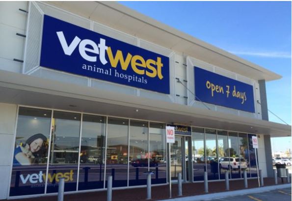
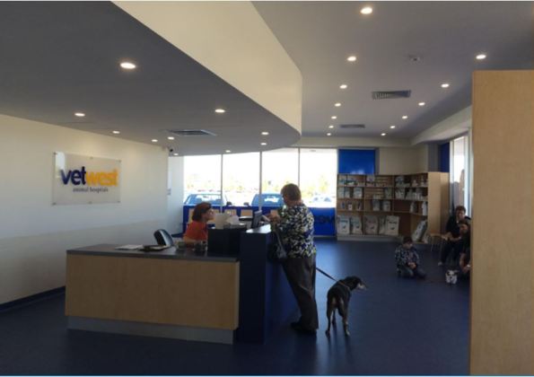
NDY – Vetwest Animal Hospital
Like the first example I have already discussed my involvement in my first project leader role on the Vetwest Animal Hospital project, see link below.
https://wordpress.com/post/htstrial.wordpress.com/11190
Now complete I conducted a feedback session on site with the construction managing contractor, Perth Citi Fitout (PCF). The reasons I wanted to do this were threefold: understand what went right, wrong or what could have gone better in order to improve where needed for the two subsequent projects that I was informed we’d most likely win; allow me to properly reflect on my first project leader role for self-appraisal; and finally to retain any lessons learnt to ensure corporate knowledge is not lost when I leave.
Overall the project was a success, testament being a number of conversations with PCF’s managing director who has praised my work and co-ordination of project leading and is looking to conduct two further Vetwest projects with NDY as the design consultants.
The biggest issue, which wasn’t really that big a deal and which was easily resolved and done so promptly, was the missed deconfliction between the supply air diffusers and light fittings. Although the lights themselves were not included in the scope of works we did have the CAD file of the ceiling plan. It wasn’t until the lighting sub-contractor began installing the lights did it become apparent that the diffusers were already installed and in some but not all cases they were where the lights should have gone. A phone call to me explaining the issue was enough to quickly go about resolving the issue. This was a chat to the CAD department requesting that the electrical ceiling layout and mechanical layout be deconflicted. There were a few knock-on effects, mostly being a number of supply air grilles that required blanking plates to avoid cold air hitting and dumping down wall surfaces in some of the smaller consulting rooms where it would be noticeable; also, the time to source and fit them. One unaffected outcome was that moving the diffusers by a ceiling tile or two was practically very simple as mech sub-contractors love to use flexible ducting running off the indoor units and they always allow a metre or so spare capacity.
The reason this issue slipped through the net was due to me making an assumption that the CAD draughty would have done this check when overlaying the various discipline layers in Revit – lesson learnt, don’t assume, ask and get confirmation.
Other smaller issues were some of the technical specifications of fixtures and furnishing were the incorrect type, for example, the back of house laundry sink didn’t fit in the cabinet as it was too deep and the sensor activated scrub sink taps were apparently the wrong type. This was again a case of not checking that the tech spec brochures provided were correct, although you could argue that this should have been a check conducted by the managing contractor when they were reviewing the design drawings. Another issue, from an aesthetic point of view, was the medical oxygen supply pipe running from the cylinder cage outside to inside was installed running up the inside of the wall from ground level to through the suspended ceiling. The core through the outer brick wall should have been located in the ceiling void and the pipe run down the outside of the wall where no one will see it. Having chatted this through with the hydraulic design engineer he said he accidently omitted the pipe dropper symbol on the CAD dwg and so the hydraulic sub-contractor literally followed the dwg – which I suppose you can’t blame him for but maybe he might have seen this type of arrangement before and should have least had a chat to the on-site PM.
As part of the same feedback session I also had the opportunity to ask questions of the clinic team manager, as Vetwest were moved in and the practice was in full swing. Astonishingly, none of the staff were consulted by the Vetwest project manager. She was shocked when I told her that this level of stakeholder management was an absolute must and should have been conducted. It transpired that on her initial induction walk round her and her staff pointed out a number of incorrectly located equipment including the unnecessary installation of a hose cock tap and floor waste bucket trap for the Cattery. Their SOPs are to simply sweep out. There was also the requirement to fit an extra oxygen pipe branch into the X-Ray room. This was something I recall having a telephone conversation about with the Vetwest project manager and remember getting it confirmed in writing. It was to be included then it wasn’t then obviously it was. The issue with it was that the terminal out the wall was in the wrong location for their trolley to connect onto and reach the dog/cat when positioned on the X-Ray machine.
A lot of this is down to a lack of internal Vetwest stakeholder engagement and is a valuable lesson learnt.
What Now?
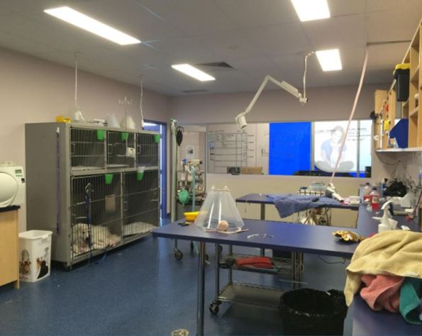
Having conducted the feedback session I am presenting these findings to the design team involved in the project and therefore closing the loop on the continuous improvement process. It also highlights the issues mentioned above and aims to ensure that whoever project leads the next two projects, they understand where to find particular information. An example being: the Australian Veterinary Association Accreditation Scheme that Vetwest was seeking to highlight to their customer base and regulatory inspectors of their attainment of best practice animal care. I achieved this through understanding the technical implications of accreditation, like ensuring cleanliness standards are as high as possible. To strive for best practice here meant installing HEPA filtration in the Surgery room.
From this….
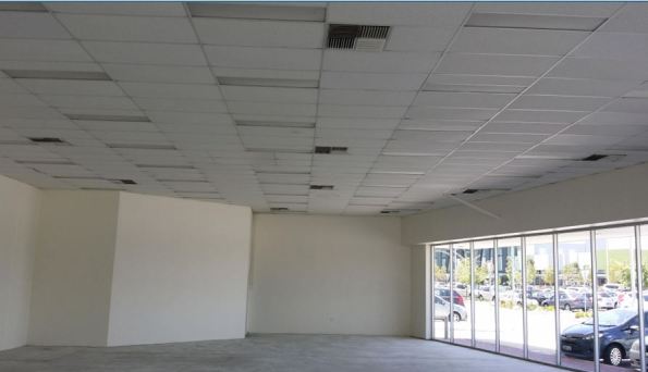
…to this.

In Other News
We’ve seen a fair amount of aquatic life, and swimming with Whale Sharks was definitely one of the highlights of our time out here.