Calling all aspiring structural engineers
Evening all,
A short and sweet post. As a lowly E&M engineer in training I am interested in some second opinions on the deflection of steel structures under load.
This week I have been occupied with installing temporary tunnel ventilation fans in the -5 level of Bond Street Station. The fans weigh around 3500kgs and will be in operation for around 18 months. The first of four fans was due to be moved into place today using a porta-gantry onto a simple steel frame.
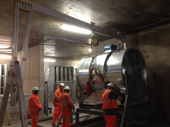
The fan being lowered into position on the support frame
Upon lowering the fan onto the support one of the operatives spotted a part of the frame deflecting under the applied load. The web of a channel section was bending inwards as the chain hoist lowered the fan, distorting the anti-vibration mounts.
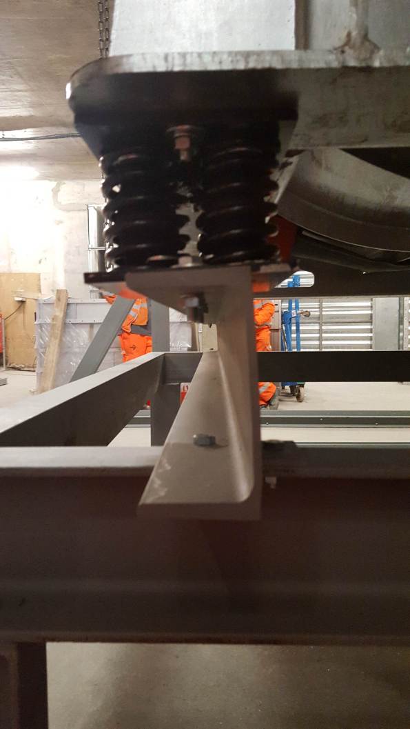
Apologies for the poor photo. If you draw a line along the top and bottom flanges of the C-section they are no longer parallel; causing distortion to the anti-vibration mounts. The lift was stopped before the full load was applied.
This would all be highly interesting except for the fact that I am only SMSTS qualified person on site and conducted the brief for the works. It also came down to me and a grad mechanical engineer to judge whether the deflection the channel was showing was acceptable, and whether to continue lowering the full load onto the deflecting frame. After some teeth sucking and discussion with the lift AP we decided to lift it back off and question the frame designers. Queue a lot of Northern blokes pissed off that they had wasted a days’ work. Reminds me of being a Troop Commander.
On removing the load the channel returned to its original shape with no permanent deformation.
Was it the right decision to stop the lift? Or can you expect visible deformation on a channel loaded in this direction? Is this the right steel section to use for this application?

Mark,
Yes you would expect a piece of steel to deflect on being loaded, and the fact that it returned to it’s original geometry on removal of the load implies it was within it’s elastic limit, but…
First is to acknowledge that the deflection was not under it’s full loading so there is little comfort to be drawn from the fact that it returned to it’s original shape and the correct response if you are concerned, and beyond the limit of personal competence, is to stop and seek advice unless the act of doing so incurs greater risk i.e. your action was definitely correct. I’ll leave it to one of the C stream to do the math on the eccentricity of the load and therefore the moment generated at the edge of the flange along the length of the channel using a few broad assumptions about section size and length….
Second is to note that the section appears to be between the mountings and a transverse piece of steel running to a leg on each corner. I can’t see what this channel section is intended to do other than act as a packing piece. It appears to lend nothing to rigidity of the support frame so your question about right for application is best answered by a question – what is it’s purpose? If you do just leave it out you may find the section below is the same geometry but because it is framed into another element at 90 degrees to it is has greater torsional stiffness and so will deflect less/differently. I would anticipate a more acceptable response but one that would benefit from a quick calculation – more information required on steel section and connections. Is there a tolerance limit on the mountings in terms of rotation of the support?
Rich,
Thanks for your rapid response. As you described the purpose of the channel section seems limited other than provide a spacer between the rest frame and the AV mounts. There is no tolerance known about the mounts; they will no doubt perform less effectively or have a shortened working life if they are not fixed level. I reckon the base of the mount needs to be fully supported by the frame, rather than overhanging the edges.
As you suggest the more rigid steel frame (below the deforming channel section) may be a better mounting point; however that solution would involve a new frame as the fan must be mounted at a fixed height. The current plan is to pursue the steel designer for confirmation of the deflections we observed – if there is a design error then a remedial solution will be sought. Current options discussed last night are:
– Fit another channel in a back-to-back arrangement (to make an I-beam)
– Replace with a box section or I-Beam.
– Replace the channel with a thicker one – the section used looks like a bending member (thin web, thick flanges) rather than something to resist crushing (column members?).
Regards,
Mark
Mark,
– Another channel section is an easy quick fix but expensive and over kill other than to deal with the serviceability failure of a single channel.
– An I section is similarly overkill but a reasonable solution, however, as Doug observes, beware the bolt hole location issues.
– A box section sorts the bolt holes out but you will not be able to access the nut to tighten the mounts – constructability nightmare! You would end up with expansion bolt fittings design for SHS which is fine but again more costly than needed.
– Thicker channel will still deflect, just to a lesser extent. Crushing or web bearing and buckling are not your issue and although a column section would deflect less and because it is H (or I) shaped will also have the same benefits of a beam section but is not really a great solution.
Jo’s suggestion of a web stiffener or a closure piece across the jaws to generate a localized box section is the normal resolve. This can be done either with a piece of plate and local hot works (if permitted) or by fixing a small section using clamp connections. If you’re working to construction drawings and there are delays associated I’d await the designers solution and make sure that they know the clock is ticking at their risk.
Having said all of that perhaps more useful would be to say go and look at Ancon Lindapter connectors and Hollobolt. either bolt another channel between the mounts with lindapter connections or switch to 150 x 150 SHS with hollobolt connectors.
Mark, can you let us know what section you are using? I suspect what you have is LTB from a load applied outside of the shear centre. Steel isn’t my strong point but, I will give it a go.
About the your call. If it doesn’t look right 99% of the time it’s not right. So your instincts are spot on. When in doubt there is no doubt.
Given the vibration that this will undertake the elastic deformation is still concerning and could lead to fatigue, but you would know more about this than me. A simple I beam would have been better choice in this case.
Doug,
The channel sections supporting the AV mounts are 150x75x18 PFC. This section is also used or the rest of the frame. Each channel is 2540mm long and rests on the frame below with an equal overlap of 127mm at each end.
Agreed about the vibration/fatigue issues. At the time we were more interested to see if the section web would fail immediately on full loading!
Cheers,
Mark
Mate I will get on it tomorrow after I’ve cleared the kinkiest and dead hookers off my site. It will give me something fun to do.
Mark, Having read Richard’s comments I too don’t understand what the purpose of using that section is. (Note the following is a bit of logical thought process brain dumped on the page)
The load transfer from the fan onto the C section appears to be roughly above the reaction given to the C section from the subframe – therefore what is the bit in the middle doing??!! Picture the cross section of the steel member ; the two loads (the load from the fan and the reaction from the subframe) both act in opposite directions roughly half way along the top and bottom flange effectively pinching the C section causing deflection. The stiffness of the section will determine how much deflection you actually see. Agree with Doug that an I section would have better suited to provide the stiffness you need but looking at the connection detail – the bolt seems to sit equi-distance between the springs, so centrally locating the springs on the section would mean the bolts would clash with the web – maybe this is why a C section was chosen. If there is a well founded reason for these members to support the fan, can you not simply stiffen the areas of the C-section which support the fan by use of web stiffeners? Obviously these would be need to be designed with appropriate welds etc but could be substantially cheaper than replacing the sections.
Jo,
Agreed that web stiffeners could be a solution, however I wonder if just replacing the current section with another would be quicker and simpler? Avoids the use of finding a welding company to do the work, getting hot works approved and set up on site, repainting the section afterwards, etc.
However, I will definitely throw it into the whirlpool of solutions that are currently flying around the office! The fan installation is quickly moving onto the critical path for the Crossrail tunnel concreting works.
Cheers,
Mark
Mark, l lack the technical insight of the above into this situation, but if I were in your situation I would have done exactly the same thing. Ninety nine times out of a hundred, if it looks like an accident waiting to happen, it’s an accident waiting to happen. From a materials perspective as well, the only reason I can think of that you would have something permenantly deformed for eighteen months is because you wanted to store energy in it for some reason. Springs used for isolating vibration are a classic example, but as these are already in place I think we can rule that out as the designers intent. The question I would be asking is were these mounts designed specifically for this task, or are they commonly used elsewhere with these fans? Whilst the Civils are sharpening their limit state skills, phone around the company and see if there are similar installations on other sites that you can use to imperially check the situation you have.
Jim,
The AV mounts came with the fan from the manufacturer; I think they are a standard item (currently searching for a data sheet as we speak). However, as mentioned to Rich I am surprised to see that they are not fully supported at their base by the ‘bendy’ pre formed channel section.
Perhaps another oversight by the steel frame designer? Task for the rest of the day is to find out if the mounts will function correctly given only partial support over the base plate.
Cheers,
Mark
Mark, in order for the mounts to work there has to be a rigid fixing on one side to counter act the dynamic forces acting on the other. Clearly a very small amount of deflection is OK, so long as the deflection is consistent during the operation of the fan that is to say it is not vibrating as well. If it does vibrate you are clearly not isolating the frame from the fan’s kinetic energy. This could result in stress fatigue (possible, but not a high risk), however, what you will definitely get is a noisy installation that may look a bit alarming as it moves (think unbalanced washing machine on spin cycle).
Mark
Drop her in – what’s the worst that can happen!
I think it starts with mountings sitting at an angle that you know they’re not meant to be at, progresses to a shear failure of the mounting bolts and ends with a non functioning ventilation fan sitting beside it’s cradle in a difficult to recover position. Hopefully no serious injury but significantly more delay and a difficult explanation.
The ensuing court cases could be a little costly and the chaps in wigs often don’t understand what is meant by balance of risk when it can be demonstrated that you knew it was a potential accident waiting to happen. on the plus side you might get a long rest and opportunity to reflect at her majesties expense (rather like the PET course but with bars on??)
My sentiments also – why are they using a Porta-Gantry? Did you not have your lifting gloves with you?
Mark
Attaching anti vibration mounts to a rigid structure through something flexible is only going to transfer the vibration to the steel section at lower frequency, cue the washing machine Jim describes as a rather nice feedback loop starts to develop. I can’t see the rationale for not bolting the AVMs direct to the frame, is this a design flaw or a simpler error? ie has the frame been made too low? Maybe a few bags of sand, cement and chippings as JM would say could raise the whole thing to the correct height !! (its more difficult than that, honest)
I think we’re all in agreement you did the right thing to halt works and reassess, hopefully you’ve got an answer to the problem.
Yep – the gut reactions are fairly good…All a bit mental really
So you have approx. 8.8 kN on spring mounts off the shear centre of a C section
Even without p-delta ( in other words assuming the C stays in it’s original shape) we have a moment and a direct force in the channel web
You could ( sort of) analyse this as a bending strut …all I’m going to do is to assume the actions distribute to about half depth of the C
Using P/A +- M/Z to get a stress of about + 90 or – 75 N/mm^2 CYCLIC because the thing’s on springs AND it’s a reciprocating load
So if you take 355 grade steel through about 1 million load cycles at normal temperature it gets to a basement yield strength of about 50% the original strength ( it doesn’t drop further ). This is called a S-N fatigue curve ( I think mecchies call it a Werner curve)
I’ve assumed the 35 kN is perfectly distributed over the four corners AND the C section does not increase the stress by p-delta- BOTH are erroneous.
We get to a yield FOS of around 2
…..I have ignored Griffith’s crack theory locally ie amplifying local stresses at pre-existing crystalline defects initialising a brittle failure
…..So good luck with that
I agree , if it looks wrong …it probably is….in this case…you’d have to be mental to think that this was a good idea
……….well done … you’re not,
Thank you John, I can follow the above and it all sounds convincing to me. Having examined the other C-sections that are yet to be loaded it seems that the deformation is either a manufacturing defect or a result of welding on the bracket at a later stage; the greater issue would therefore be a fatigue failure later down the line.
You will be glad to know that the final solution has now been agreed upon with the installation contractor- replace the channel with a box section. This has the same dimensions as the channel it replaces except it is wider – supporting a larger proportion of the AV mount.
Many thanks,
Mark