Archive
The value of 3-D Modelling and record keeping.
The majority of my time on phase 3 has been focussed on working at the London School of Hygiene of Tropical Medicine (LSHTM). LSHTM’s building was opened in 1929 and has undergone several overhauls and extension over the last 80 odd years. This combined with the fact the keeping of record drawings seems to have been considered as an embuggerance as opposed to good practice made working out how I could modify their systems a bit more tricky than it needed to be.
If LSHTM were to be considered as left of arc, I have more recently been working on a project at the right of arc end of the spectrum; the re-modelling of Circle Reading Hospital which I have previously blogged on. The scope has now been expanded slightly. The client now wants to change the use of a waiting /reception area to a group activity (physio) room. This has implications with regards to the level of ventilation required to the space and the cooling load required. Although not contractually completed to a specific BIM level, Circle Reading was designed in Revit with the associated Navisworks models still in existence. This has allowed me to quickly interrogate the model via a desk top study to see what is supposed to be in the ceiling void and work out what space and services we have to play with. The client’s F&M team have also been very good at keeping records, so I have been able to interrogate the original main contractor’s commissioning results and compare them against the original design specification and schedules. From there it has been a case of applying the necessary calculations to work out what the new load is, confirming if the existing system has sufficient spare capacity and in what areas modifications need to be made to allow my proposal to work. Of course all this would have been possible without the information I was given, but it would have required hunting around the building for equipment details, getting airflow velocities and getting into ceiling voids to see what is actually there. The use of 3-D modelling and good record keeping has allowed me to meet the client’s intent of getting a proposal out cheaply and quickly. There will be significant caveats applied to my design note as I’ve not confirmed my design start point on site; however, the client is aware of this risk and happy to proceed.
Poplar Island
Poplar Island
So, I’m actually on site now doing some engineery type things! However, for obvious reasons taking photos is proving to be a bit problematic. In order maintain some sort of presence on the blog, welcome to my new two part mini-series, which I’ve catchily decided to call “interesting things that USACE do that the Royal Engineers don’t do”! Location one: Poplar Island.
Poplar Island was/is an island in the middle of the Chesapeake Bay, approximately 18 miles south-east of Annapolis. Historically it was settled in the 1630s, and had a permanent population all the way up until around 1920. However, due to a number of reasons, mainly human mismanagement, but also natural erosion, the island shank from approximately 1000 acres in the 1840s to less than 5 acres by 1990, and was set to disappear altogether had someone clever not decided to do something about it. A vast amount of material is dredged out of the Chesapeake Bay each year in order to keep the shipping route to Baltimore open, and some other clever person decided it might be a good idea to use this material to try and stabilise and rebuild the island.


Poplar Island During Construction (bottom photo is probably 2 or 3 years old)
What has been achieved since then is one of the best examples of ‘environmental’ engineering that I’ve ever come across. Since 1998 USACE have created 1140 acres of ‘new’ wildlife reserve in the middle the Chesapeake Bay. The technique they use is to create a series of waterproof bunds that divide the ‘island’ up into manageable ‘cells’. They then pump millions of litres of sediment rich slurry into the cell they are working on, allow the slurry to dry out, then repeat the process for as many times as is necessary to build up the amount of material required for the habitat they are trying to create. The two habitats being created on Poplar Island are ‘tidal wetlands’ and ‘upland woodland’ in about a 50:50 ratio. When we visited last month a number of the tidal wetland cells had been completed, but all of the uplands cells were still ‘work in progress’ because they require the ‘finished floor level’ to be significantly higher!

Completed ‘Tidal Wetland’ Cell
Whilst generally successful the tidal wetland cells that have been completed so far provided some challenges, mainly for the biologists creating the habitats. Initially the channels linking the ‘inland’ water and marshes to the bay were too small and discouraged the large predator fish species from entering which led to an unbalanced ecology. Subsequent cells have been designed with larger openings and have been more successful.
So far the island is frequented by around 175 different species of birds, including ospreys, and terns. The terns are interesting; despite having over 1000 acres to choose from, they are habitual, and so return every year to the same tiny section of the island that they have always used! The biologists are hoping they’ll eventually get the idea, but so far they seem happy on their little patch of mud. The ospreys are currently living on ready-made posts, but the plan is for them to move into the trees once the woodland sections of the island are far enough advanced. A significant colony of terrapins has also established itself on the island which the staff are particularly happy about!
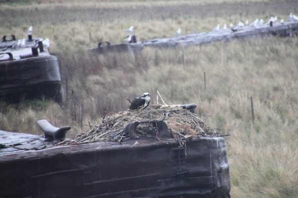
Local Inhabitants (Osprey)!
From an engineering point of view project is interesting, but really relies on the sheer volume of material for success. Now that the techniques have been tried and tested there is little in the way of complicated problems to be solved, and the process is very repetitive. The one issue the project did have was when one of the bunds was breached/overtopped during a particularly bad storm early in construction. This led to a significant amount of material being washed away and the bund having to be reconstructed before work could re-commence.
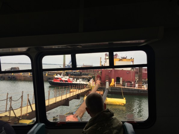
Henry’s Head (and the pumping station from where dredged material is pumped to the cells)
The total cost of the project is set to be around $800m, of which 75% comes from the Federal Government and 25% from Maryland State. The scheme has proved to be so successful that plans are well advanced to add a 575 acre expansion to the north of the island which would take the total area to approximately 1700 acres. The ‘construction’ phase is currently due to be completed in 2029, however significant management would be required beyond this date. If only the Royal Engineers were trusted to deliver something like this!
Other News
I’ve inherited three Officer Cadets! They were recently sent out on a two day ‘recon’ to gather ‘intel’ on some local critical national infrastructure! I very much enjoyed listening to their backbriefs and grilling them ‘Warfare Wing style. The next “interesting things that USACE do that the Royal Engineers don’t do” blog will be on the Raystown Dam and reservoir, an equally colossal project!
AEH.. “INFO ONLY”…
Hello folks, just a short, sharp snip it of some interesting bits going on in the design office here in Sydney’ M4 East motorway project. Clearly, those two terms are rarely linked but today I think they make the cut.
“Info Only” – Interesting proposal by AEH (AECom & Hyder JV)…Clear lack of comms…
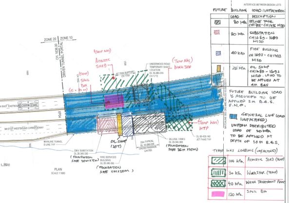
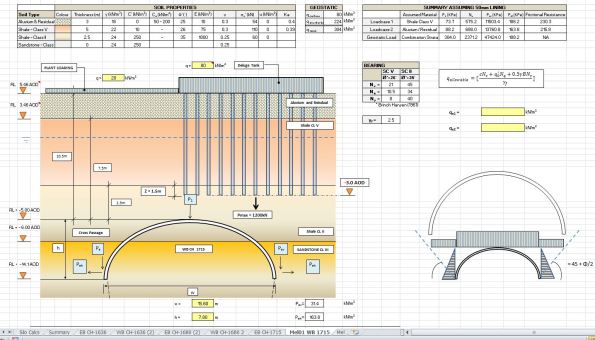
Attached below are two images. 1. Plan of mainline tunnel with surface loads indicated. 2. A screen shot showing the proposed AEH foundation design within a section of mainline tunnel I was analysing for crown loads and canopy tube design. The confliction with our 4m rock bolts emanating out from the tunnel lining is not show.
AEH released their package today for various permanent M&E structures to be installed above the tunnel. I’m in the process of assessing the shotcrete lining thickness and elephant foot dimensions based upon surface loads, overburden, relaxation, ground water etc… The original idea was to install a raft foundation which we were more than happy with (10.5m above). The fact that they now wish to terminate their piles 2m above the crown of the Westbound mainline tunnel is one thing… the fact that they only put Macmillen Jacob Associates (MJA) down as “INFO ONLY” on the cross discipline review form is another! Unbelievable…
Presumed next step..Cost analysis to compare the additional excavation + lining thickness + time+programming required to support new proposal vs an reconsidered AEH foundation design. Interesting stuff but clearly not my main priority at the min…
108 Update
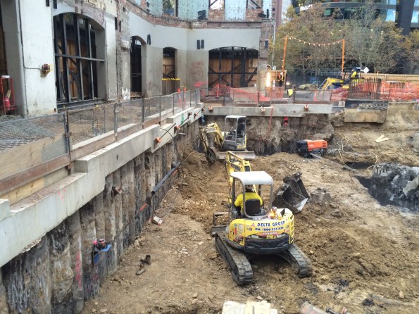
Time for an update on site progress at Australia 108. Lots of progress on site this week. 90% of the piles caps are complete and we have begun the excavation to Basement Level 1. We are 38 days behind the site program due to various issues and delays with the piling as well as lost days due to weather.
The most recent big issue is one of out-of-tolerance as-built piles. The Australian Standards allows for 75mm tolerance however due to the risk in the piles, the designers have allowed for 150mm. So what do you get when you discover that a 2100mm, 80MPa pile with a design axial load of 111.6MN, moment of 16.5MN and shear of 2MN ends up being 401mm out of position? An increase in moment to 49.9MNm; the design effect has greatly exceeded the design resistance of the pile = big problem! The engineers are currently looking at rectification methods involving large transfer beams in lieu of individual pile caps and transferring the addition moments generated to the other piles and the core if necessary. It is estimated to be at a cost north of AUS$400k = 200GBP +. There have been 12 piles over the specified tolerance and with the exception of one, the others have luckily had adequate capacity to resist the additional moment due to the redundancy in the pile with minor rectification measures being introduced to the ground beams.
My TMR is looking into the risk management strategies of deep foundations so once I’ve finalised it, I will post a very abridged version highlighting our issues and probably causes. I know a few of you are soon to commence piling in your projects and can benefit from hindsight of some really simple errors that have been made on this site – most of which could have been easily avoided.
Here are a few pictures to keep you up to date with progress on site.
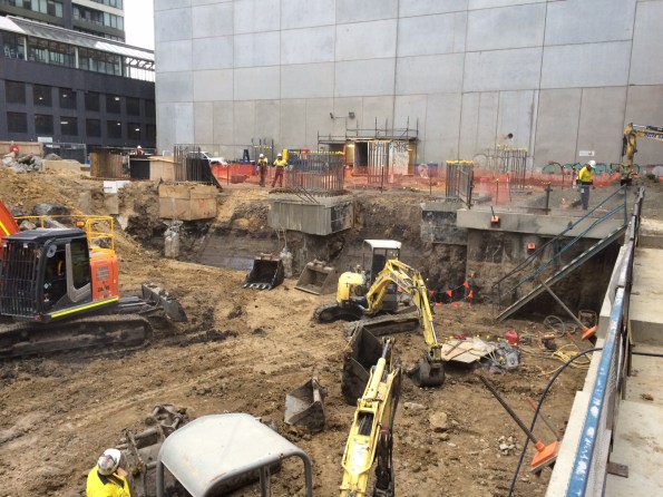
View to the East

View to the South – excavation of the core piles has begun consisting of 16 x 1800mm king piles with 600mm dia CFAs between

View to the West – secant retention wall to protect a 60 yr old heritage facade at the northern end of the site
View to the North West – northern retention wall and one level excavation
And for those of you with beady eyes it will not escape your attention the 3+m high vertical face of the southern end to the excavation. Fine grained soils, 30t excavator rolling back and forth on the top of it and no retention or batter. We’ve also had a lot of rain recently (for Melbourne anyway – the news reported a taxi getting flooded out to mid-point of its wheels!!!!!) I have raised this concern to the powers that be and it has already been mentioned to the subcontractor who have chosen to continue as it – because they do it all the time. BMC are allowing them to continue (cynical view – because any changes will slow down progress.) They have instigated no one to walk at the foot of the wall yet people are still walking at the top of it. I’m astounded that they will stop work for the slightest speck of rain because of the potential hazards created, yet they will let people walk along the top of an unprotected excavation. And they are constantly telling me how at the forefront of H&S they are. Barking!
Progress on 12/5/16


Progress of 13/5/16


Circle Reading Remodelling
The most recent work strand I’ve been involved with at BWL is the re-modelling of a private hospital in Reading. The hospital is owned and run by Circle who have a long term relationship with Bryden Wood Ltd (BWL). The requirement to re-model is based on Circle wanting to go into a joint venture with a German health care provide called Vamed. The plan is to hand two of the four floors of the existing hospital over to Vamed. This requires a number of rooms on the second floor to be changed. The client’s drivers are cost and time. Initially BWL priced the job at £90K for an architectural and M&E design role. The client currently doesn’t have a formal agreement in place with Vamed, so the real driver is to get the work done in order to seize a potential opportunity whilst spending as little cash as possible. This has led to a reduction in BWLs fee to £10K, which means BWL’s outputs are limited to a concept design which will be taken forward by the main contractor. I can understand the financial pressures the client is under, but it seems a little odd that the first interaction in a future strategic relationship is being done on a shoe string budget.
From an M&E perspective there are 2 engineers working on this project (1 electrical and 1 Mechanical). The limited budget means that this work needs to be turned around quickly, which is great for me as it’s another project under my belt for CPR.
What has my role been:
As the sole mechanical engineer working on the project I’ve been responsible for checking the implications of the changes of use on the mechanical system. This has entailed:
- Producing room data sheets for each area to define the environmental standards that need to be met (ventilation rates, temperature, acoustics, etc.)
- Using the data from the room datasheets to calculate loads for each area (cooling, heating, ventilation, domestic cold water, domestic hot water)
- Identify the best possible way to meet the new demands. As an example active chilled beams are utilised to provide comfort heating and cooling, where possible these have been retained, but where loads are too great or not close to the current distribution network other solutions have been provided.
- The impact of these solutions have then been confirmed: basically checking pressure drops in pipework and ductwork and making alterations where required.
- Engaging with my electrical and architectural colleagues to ensure that our designs are co-ordinate.
- This has then been pulled together into a scope of works, including mark-ups of existing schematics and schedules of new equipment so that the contractor can price the job and take the design forward.
All in all a good little project that has given me some solid B and D competencies. It’s probably worth noting that I found the calculations involved in conducting this work to be much simpler than those conduction for phase 1: phase 1 more than prepares you for the technical aspects of phase 3.
Temporay Tunnel Ventilation Problem
As well as getting my head around the intense amounts of jargon I have been occupying myself with a problem facing the tunnel ventilation team.
Here is the BLUF: Each tunnel (East and Westbound) contains a couple of dirty diesel-powered locomotives and a workforce occupied with drilling holes in the wall. The upshot is that the air quality in the tunnels has the potential to become very poor as the M&E fit-out work progresses, and the permanent ventilation system is a year away from commissioning.
My placement company (ATCjv) are charged with the temporary ventilation to prevent this becoming a big problem. Unfortunately they are also preoccupied with the permanent M&E fit; as a result the temporary works are getting relatively little attention. The permanent ventilation fan system is eventually designed to provide 100m3/s into the tunnels at each station when running at steady state; in the case of a fire or terrorist gas attack it can blow or suck 600 m3/s at full whack. This is enough to create a 9.6 m/s (21 mph) draught down each of the two tunnels.
However, whilst each station is under construction the main ventilation fans are months away from being installed; the ATCjv ventilation team need to provide a flow from Bond Street station to give sufficient air quality for the workforce in the tunnels. The flow diagram of the temporary ventilation installation is shown in figure 1.

Figure 1. Bond Street section temporary ventilation flow diagram
The interim solution at Bond Street station until a large-scale temporary system is commissioned is to fit a 250 kW forced ventilation fan into a tunnel feeding the main running track, an image is shown in figure 2. The flow rate of ventilation air through this fan is measured using an anemometer held in the flow– not a particularly scientific or reliable method. Ideally the temporary solution will give a flow rate that is comparable to the finished station; the current measured flow velocity in the fan jet is around 24 m/s, giving a volumetric rate through the fan (velocity x area) of 8.64 m3/sec. This is way too low to meet the temporary requirement of 35 m3/sec. The solution is to rely on the noxious gas detection equipment with the workforce in the tunnels as a safety net and take the problem ‘on risk’ (i.e. no-one important has noticed yet).

Figure 2. The temporary ventilation fan in its feeder tunnel.
The final ventilation system will be commissioned with a much more rigorous ‘grid’ system of anemometers to measure the flow velocity throughout the tunnel cross-section (see figure 3 below) which will give a much more accurate flow value. However this hasn’t been applied to the temporary system – it is too expensive.

Figure 3. Approved tunnel ventilation measurement methodology. Survey points on tunnel cross-section show anemometer locations.
To keep myself useful I have tried to figure out a more accurate figure for the ventilation flow than given by the current improvised method. The ducted fan acts to fire a jet of high velocity air down the centre of the tunnel drawing further air with it from the surroundings (air entrainment). This has the effect of increasing the airflow down the passage. To add some detail I have tried to improve upon the simple flow model by considering an annular boundary layer around the ‘jet’ of high-speed air, as shown in a dodgy sketch below (figure 4).

Figure 4. Flow pattern from the ventilation fan, back of fag packet version.
V1 in the image above is the peak flow at 24 m/s, with the air velocity at the edge of the fan ‘jet’ being 8m/s. Using this new approximation a revised estimate of the actual flow taking into account entrained air through the 3-meter wide tunnel is 19.32 m3/s. Still off where it should be, but a little bit closer to the desired 35 m3/s. The construction manager posed with this solution was simultaneously pleased that it was larger than his number and completely unconcerned as to the reasoning behind it.
I hope at least Mark Hill was happy that I actually tried to apply some of the knowledge he threw at us in the second half of last year. Please consult Palmer TMR 1 for a more detailed description of where this figure comes from…. if you can stay awake.
CI’s thoughts on blogging…
I thought that a blog from the CI to offer some thoughts on attachments and blogging may help to ameliorate some of your concerns that I have been picking up during my discussions with you.
My first top tip is to focus on the endstate – successful CPR. For those of you on Phase 2, you have over a year to complete all of your UK-SPEC competences (or attributes for you Cs as I have now been informed that development objectives are no longer in vogue…) Do not feel concerned that you might not be being exposed to huge technical detail during your site attachment. Be concerned if you are not being exposed to good commercial, financial and project management detail. The technical stuff will follow on Phase 3. If you are on Phase 3 and are experiencing a bit of ground rush, now is the time to really check your development action plan and ensure that in the last couple of months you close the gaps you have identified in your experience. I am sure that all of you are in a good place in this respect though; that is what AERs are for, to track progress and aid your planning of your attachment. Remember that this is an MSc and that you are all captains or majors working towards being chartered engineers – you own your journey.
My second tip is don’t just feel the need to write about your positive experiences. An important part of being an engineer is to be able to reflect and understand one’s limitations. Therefore, please do not hesitate in writing about your challenges, your incomprehensions and your failures. You will be a better engineer for it, as will your peers and as will we be as staff. Your blogs are some of the best CPD we have experienced.
Hence, the value of your attachments is in the journey taken to the endstate and what you extract from it. Some of the most valuable experience gained by students has been from small tasks, where a complete view of the totality of an issue can be seen. There is no need not to blog because what you have been doing is not as sexy or as complex or as large scale as the previous blog. The important element is what lesson or experience or development point can you extract from the experience? So blog away without inhibition (on professional engineering matters of course).
Most importantly: Enjoy the experience and size the opportunity!
SRL
Bruce C16 Caisson Swage Repair
 If the title of this blog makes absolutely no sense to you then you’re at the same starting point that I was when this project was handed to me! This project is currently the top structural integrity concern in the BP North Sea portfolio but is actually relatively simple once you get your head around what’s involved. The project pretty much covers all the core competencies, focussing mainly on contractor management and project management, with a good dose of health and safety due to the nature of the offshore industry and some complex lifts which are required.
Background
A caisson is effectively a big pipe which extends from the deck of an offshore platform down to below sea level. Its purpose is to minimise the effect of waves on seawater lift pumps (seawater being the obvious choice offshore for cooling, processing and fire fighting).
The BP Bruce asset, comprising of separate drilling (D) and process, utility, quarters (PUQ) platforms is located some 200 miles East of Aberdeen and was built in the early 1990s. The PUQ platform has a number of caissons which are shown in the images below and right (circled in the photo and labelled with hexagons on the drawing). The dashed lines in the drawing are the jacket (support legs and bracing) of the platform. The caissons are attached to the second horizontal brace down. Sea level is approximately at the midpoint of the top set of cross bracing.
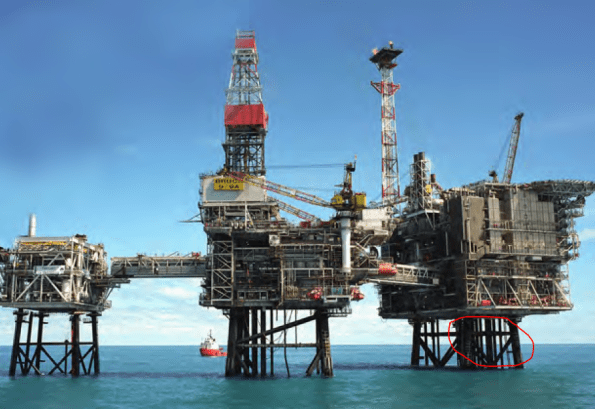
BP Bruce Asset (Seawater Lift Caissons Highlighted) & Jacket
Due to a combination of the age of the asset, climatic conditions and the corrosive nature of seawater, structural integrity is a constant challenge. The point where the caissons on Bruce are attached to the platform is the point of greatest stress and corrosion and caissons C12-C17 have suffered major cracking (example shown below in photo). Why this is such an issue is due to the ‘dropped object’ risk. If the caisson were to break at the crack then 30 m of 1 m diameter steel pipe would plummet towards the seabed. There is a risk if this happens of damaging nearby caissons (and therefore the ability to fight fires), the jacket (therefore putting platform integrity at risk) or equipment on the sea bed (therefore putting production and hydrocarbon containment at risk).

Bruce Caisson Crack
Options
In order to address this risk BP considered 2 options:
Option 1 – Replacement. This is something that Imran was working on several years ago and was cancelled due to cost. Replacement would involve procuring a new caisson and all the related deconstruction, transport and construction works. This represents a significant investment; whatever you think it will cost, add 3 zeros in cost and triple your time estimate for offshore! In the current economic climate costs are being minimised and so this option is unlikely to be funded. Equally the life of the new caisson would far exceed the expected life of the platform and greatly reduce any return on investment.

Swaging Tool and Liner
Option 2 – Swage Repair. This is the option chosen and the one which I will be responsible for executing offshore. First the caisson is internally cleaned using a tool which utilises a high pressure jet of water to remove marine growth and corrosion. An internal liner is then lowered down over the crack before the swaging tool is inserted (see image). The tool is pressurised to expand the liner beyond its elastic limit whilst remaining within the elastic limit of the caisson itself. The liner is thus held permanently in place and seals exactly to the shape of the caisson. The process is illustrated in this handy video.
The Project
The main contractor for the project will be BP’s engineering partner, Wood Group PSN (WG PSN). Two specialist sub-contractors (known as ‘vendors’ due to BP’s global nature) will be involved. Sparrows are an offshore lifting contractor and will be responsible for the lift plans, rigging and executing the lifts (example shown in image below). Oil States, an offshore engineering specialist, own and operate the swaging tool and have fabricated the liner. I recently attended the 6 week constructability review where, as the client, I approved WG PSN actions thus far and the offshore execution schedule. Additionally I have carried out the project risk assessment in line with BP’s risk matrix and HSE guidance. This led me to identify the risks associated with the lifting and I have raised these with Sparrows. As this is the third project in a series of 4, the remainder of the risk assessment related to on-going risks and those identified previously.

Example of Complex Lift Procedure
The C14 caisson on Bruce underwent a similar repair in September 2015 and the procurement for the project included that which was required for C16 and C15 (I will likely take on C15 as a project once the C16 repair is complete). The liner and additional fabrications required are currently in storage and I am assured they will be inspected and re-certified prior to project mobilisation. Mike has blogged previously about some of the issues with materials going missing offshore so this is an area of concern for me. Other than a substandard bill of materials I was handed in the 6 week review I have had no issues so far.
Other concerns relate to the site itself. The laydown area outside the pump room where the swage repair will take place is fairly tight for space (see image below). I am competing for time in the asset schedule with another project which also requires the use of this laydown area. This, combined with the fact that the crane needed to lift my containers onto the laydown area is out of action until 4th July is already causing project delay to creep in. I will shortly be having a meeting with the other project team and the asset engineering team to de-conflict the projects and discuss the crane issue. The meeting may also see the scope of my project expand to include the C15 repair immediately after C16.

Bruce Laydown Area
Finally there is one fairly show stopping problem with this project in that the very expensive, vendor owned swaging tool might just get stuck in the pipe! Luckily Oil States have a procedure for this and the tool has a number of shear pins which can be broken by using an over pull tension in the lifting cable. Unfortunately the overhead gantry crane in the pump room is not rated for this. Fortunately a ‘strong back’ frame was fabricated for the C14 repair, which combined with some big jacks can be used to produce the required tension. Unfortunately the deck plates on the floor of the pump room aren’t robust enough to support the strong back frame. Fortunately some large steel plates were fabricated for the C14 repair which can be placed on the deck to spread the load. Suddenly it can be seen where the extra cost and time comes in for offshore projects!
Summary
So yes, that’s it, after months of the PET course and highly technical study, I have been placed in charge of a project to put a pipe inside another pipe! There is a lot of de-confliction which needs to happen to get the project mobilised but I have taken over at a time where the onshore execute phase is all but complete. Next month I should be offshore during the swaging process and will report back on the offshore execution.
Podcasts
Following on from the recent CPD theme another avenue for easily accessible CPD is podcasts. I have started to become a bit of a podcast enthusiast since starting phase 2. Mainly to fill my 2 hour commute after repeats of the Taylor Swift album became a bit too much. Clearly there is a wealth of podcasts out there and I have to confess that I have only recently realised it is a good way to get some CPD in. There aren’t a huge number of engineering ones that I have found so far but in the interests of kicking off a list that others could add to here are a few:
NFPA: This is from the National Fire Protection Association. The organization is based in the USA, where they are neurotic about fire, and provides updates on their codes and digs into other topics. I wager that the US are a way ahead of us in considering fire protection so it is worthy of a listen.
HVAC 360: You guessed it, it’s about HVAC. Presented by a commissioning agent he explores issues and technologies. I have listened to a couple and both were interesting.
Another potential is ‘The Civil Engineering Podcast’ though I haven’t listened to it.
One to avoid is ‘Engineers and Coffee’ as it appears to be about computer programming. I listened to about 10 minutes of one episode before I fully confirmed I had no idea what they were talking about. If you speak binary or java script then you might be able to keep up…
For a slightly wider audience ‘Freakonomics’ is an interesting podcast. It explores a wide range of interesting topics with a critical eye. If others have relevant ideas, add them to the comments.
