Archive
One for the Cs.
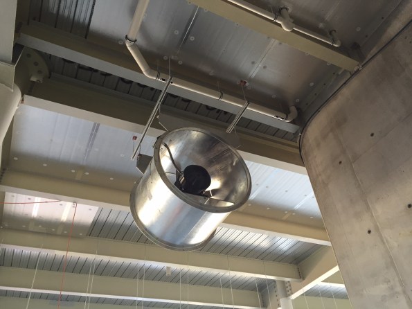
Since arriving at the ‘New Perth Stadium’ I have spent the majority of my time on site – predominately to top up my ever improving glowing tan, but also coordinate an entire services install on a $1.4 Billion 60,000 all seater stadium. Last week, while stood in the middle of a disagreement (read massive punch up) between the blockwork and plumbing foremen, I noticed our mechanical air side contractor had started hanging fans and attenuators. See picture below.
This led me to ask a few questions – how heavy are these items? How are they hung? Were there any constraints? Weight limits? I also remember how poor concrete can perform in tension so thought I’d better act on my initial concerns and investigate further.
The current slab detail is simply made up of Bondek and poured concrete as detailed below: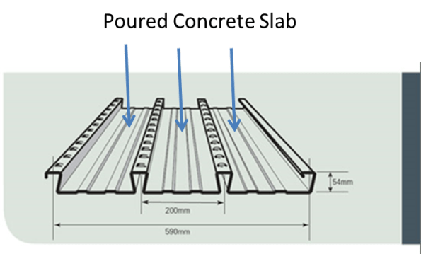
SOP for hanging fans involves drilling a 50mm hole through the Bondek and poured slab, before driving in a M10 drop in anchor which simply splits open at the top to provide a means of attaching a hanging rod.
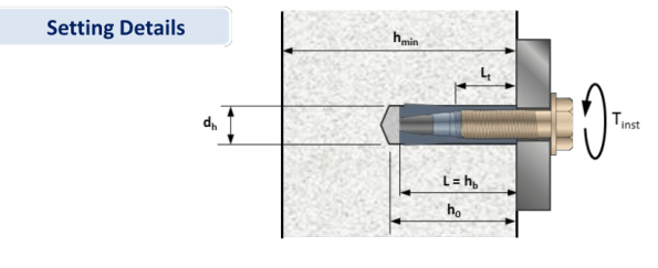
So simple, even the E&M arm wrestling champion understands….Safe working load in tension for each item are published as:
Drop in Anchor – 3.4kN
Hanging rod – 10kN
Therefore if a fan is hung as per the photo with four anchor points, one could assume a weight limit of 1360kg. [(3400/10)*4]. Luckily (or unluckily) the Icelandic Arup Structure Consultant sits next to me, so I thought it prudent to confirm my findings before giving the green light to install 60 enormous fans.
His response didn’t fill me with confidence “go ahead and install the fans/attenuators which weigh between 200-300kg, heavier items may require secondary steel.” I AM YET TO GET THIS IN WRITING! This left me with further questions and additional concerns – not least how long is this steel going to take to design, how long before it is installed and who is going to pay for it? Services install is months behind schedule and I fear this issue is only going to compound our woes! What is more concerning is that I have no doubt that our mech air side contractor is ignoring all advice and hanging everything as fast as they can in order to knock off at 1430hrs. Welcome to WA. Best get back on site…..
The importantance of off-site inspections
Nothing significant to report on my site as we haven’t started the installation yet and so we are still in the process of procuring and reviewing RAMS. Personally I have a plant movement package out to tender with the supply chain and I am in the process of reviewing tender returns for AHUs, and procuring some steelwork for some chillers and cooling towers as well procuring a temporary ventilation system for a tunnel – which is turning into a bit a nightmare as the current design does not sit well with the insurers (yes this will become a future blog……..).
Anyway I thought I could post another blog about off-site manufacture and modularisation focusing this time of the importance of off-site inspections.
Yesterday I visited Skanska Fabrications in Slough where 22 pre-fabricated tunnel modules are being manufactured. These modules will be used to for chilled water, high grade hot water, low grade hot water, domestic water, low voltage, high voltage, data and fire alarms. Each module is 3.2m wide and 6m long and weighs 4000kg and to give an idea of the scale of these goliaths, the picture below shows one module and the lower large orange-capped pipes are 400mm in diameter – so not small!!
![IMG_0382[1].JPG](https://pewpetblog.com/wp-content/uploads/2016/06/img_03821.jpg?w=595)
The first tunnel module nearing completion
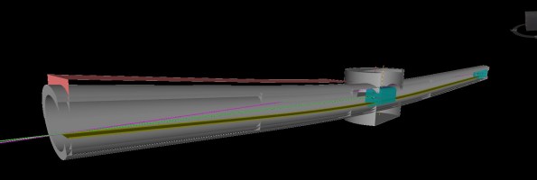
The BIM Model used to develop the installation method (note the centre shaft, winch cable lines and differing inclines)
These modules were designed using BIM and BIM also was used to simulate the modules being moved by a winch to ensure there was enough clearance in the tunnel for the winch cable and also to calculate the size of the walkway to ensure the winch cable could be ran through the centre of the installed modules in the latter stages of the installation. A picture of the BIM model showing the winch cable analysis is above. Since the modules were designed using BIM, every part of each module has its own asset code and a QR code sticker is placed on every pipe section, tray, bracket etc. These QR codes can be read by our iPads on site and they are linked to the BIM model using Naviswork BIM360 Field meaning that if I required any information about a component during installation all I have to do is scan the QR code with my iPad and I will be provided with design data, flow rates, mass, supplier and several other data sets. I have been very impressed with this system so far.
It is my responsibility to install these modules in the 132m, 4m wide tunnel and so I am regularly visiting the factory to check the quality of the finished product and identify any issues so changes can be made prior to delivery to site. One of the first issues that stood out to me was the lack of lifting points and winching points and so the fabricator is going to develop a suitable design solution and I will arrange a factory visit for the lifting Sub-Contractor to check the design and final fabrication.
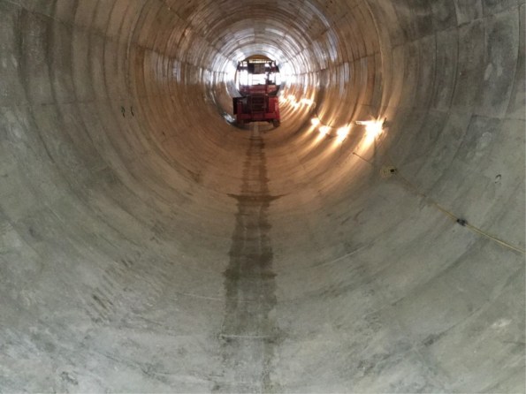
The tunnel nearing completion
The second fabrication issue that became apparent during my visit was the use of corrugated kick-plates which prevent the floor panels from being lifted out, significantly hindering future maintenance. Again the fabricators are going to redesign these and opt for a flat kick-plate.
Another issue is whether or not the modules will slide down the 0.537 deg slope under their own weight. The Project Manager responsible for this design was adamant that they would slide as PTFE slip pads are used between the modules and the rails but I was confident that they will not and this debate has been going on for several weeks. Anyway rather than guessing I decided to use some GCSE physics to calculate whether or not it would slide. My calculation was that it would not and in fact it would need a 1.7kN force to get it moving. This for me was one of those moral courage moments as I did not want to blatantly challenge a senior PM but if it didn’t move, it would be my problem to resolve on site and the requirement to push or winch the first modules would fall outside of the package scope and would incur additional cost. So I was keen to mitigate this risk early to reduce costs and avoid any unnecessary delays.
So this short visit has confirmed to me the importance of off-site inspections and inspecting a physical product rather than purely relying on a BIM model.
I thought this post may induce some debate over the benefits of this pre-fab approach. The client and senior leadership team seem very happy with it but I am not convinced. The main issue with this design is that we have to wait until the tunnel is completed before installing the modules where as if we were using a traditional installation, we could be mounting brackets, trays and pipes directly behind the slip formwork as it moves along the tunnel, casting the secondary lining. Plus looking at sustainable development, these modules will be a challenge to remove when the product reaches the end of its life as the centre access shaft will be capped and backfilled. Also I think the module frames will make maintenance much more difficult. Thoughts?
On a personal note, I have got my aircraft flying again and so I am once again terrorising the skies above Essex and Hertfordshire. I would therefore recommend avoiding flights out of Stansted or Luton for the foreseeable future.
![IMG_0200[1]](https://i0.wp.com/pewpetblog.com/wp-content/uploads/2016/06/img_020012.jpg?w=294&h=220&ssl=1 "IMG_0200[1]")
![IMG_0358[1]](https://i0.wp.com/pewpetblog.com/wp-content/uploads/2016/06/img_03581.jpg?w=293&h=220&ssl=1 "IMG_0358[1]")
Covering your back or am I just being cynical?
I’ve now completed my handover of the London School of Hygiene and Tropical Medicine (LSHTM) steam replacement project. Bryden Wood Ltd (BWL) has completed the design, which has been approved by the client and is waiting with all the other tender documentation to be issued for the selection of the principal contractor. Except if I were a betting man I’d put a reasonable wager on that this project won’t be put out to tender anytime soon. Why?
As I’ve previously mentioned steam is currently generated at basement level and supplies autoclaves within the school, serves as a backup heat source for LSHTM and also feeds a district heating system (which is not utilised). What I’ve not gone into is the contractual relationship of this setup. LSHTM don’t own the steam generators, even though they are within their building. They’re owned and operated by an FM company called Cofely Ltd who use them to provide resilience to a district heating system and also sell steam back to LSHTM for use in the school’s autoclaves and backup heating. The brief BWL received from the client was to replace steam generation for the autoclaves and LSHTM’s backup heat source, not for the district heating system. We’ve done this. The client was going to formally / had already informally confirmed with Cofely that Cofely no longer required steam to the district heating system and that LSHTM would no longer be buying their steam from Cofely. What has become apparent is that this plan was based on conversation that had been conducted by LSHTM’s estates director, a man who has now jumped ship. This has left the LSHTM’s estates programme manager with no top cover. What if Cofley decide they do need a steam supply to their district heating system? BWL’s design will need a complete overhaul. Even if Cofley are still happy to lose the district heating system they will presumably want some form of financial compensation to offset the loss of income associated with no longer being able to sell LSHTM steam (although this will be offset by not having to maintain the steam generators). LSHTM’s team don’t appear to be clear on what their exact contractual position is with Cofley, so there’s a whole load of uncertainty to be resolved.
A new estate’s director has been appointed and has put all planned projects on hold until he as personally reviewed them. This should have seen the steam project being reviewed a couple of weeks ago; it hasn’t. I recently had a chat with the estates programme manager who told me that the review of the steam project was being put on hold as there a few large capital projects due to start and they were at risk of taking on too much at once. This could very realistically be the case or it could be that the programme manager doesn’t want to expose to the new director just how much of a mess the contractual position with Cofley is. The large projects serve as a great excuse to delay and get the house in order.
So what?
From my point of view this is a classic example of ensuring you conduct your stake holder analysis and identifying the critical factors for success. From BWL’s perspective they’ve been paid for the work that had been done, so there is no loss and LSHTM are offering BWL additional work (which was the main aim of this project).
The Backfill Problem
My role within the NLE project has changed somewhat over the last week. After 4 months focusing on the construction and excavation of the Crossover Box I am now the package manager for our piling subcontractor. A great opportunity to sign off some key commercial ICE attributes.
But no less than a day in the chair and I was already trying to problem solve a potentially costly issue.
The Issue
On one gridline, the diaphragm wall cut-off level is 10.4m below ground level. This wall lies between the escalator access and will form the ticket hall. It affects 135m of diaphragm wall. The question is, what do we backfill the excavation with once we have completed concreting?
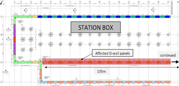
D-wall panels with lower cut-off level
The usual practice would be to backfill the excavation to ground level by concreting above the cut-off level. However not only is this a large volume of concrete (can be expensive) but it will add untold days onto the programme in breaking out C50/60 (cube strengths have been achieving 80 N/mm2 @ 28 days a.k.a. rock solid) concrete. The situation is made slightly more complex as 16 of the 45 panels contain plunge columns.
The key issue is the stability of the piling platform, this needs to be maintained whilst backfilling with a solution that will self support, won’t be too difficult to remove and can be used throughout.
What are our options?
Gravel – This wouldn’t compact enough and apparently can induce a moment on the column whilst the concrete is still green.
Self compacting gravel (pea shingle) – Wouldn’t self support and would all flow out when the stop end was removed for the excavation of the adjacent panel.
Grout – Too expensive to be a viable solution, it would require 1685m3 (135m x 10.4m x 1.2m)
Soft mix (around C10) – An option but would still require breaking out.
The proposal 1
Considering that the difference in level requires a sacrificial cage that is used to hold the reinforcement at the right level we do have a framework to work on. The initial thought was if we could concrete just the end next to the stop end. This would need to be tied as once the stop end was removed there would be very little holding back this column of concrete.
The plan so far is to install a ‘sock’ or geotextile to the sacrificial cage. Self compacting gravel will then be filled inside and outside the sock. When the stop end is removed some of the gravel will fall into the excavation but the majority will be held by the sock.
The proposal 2
The addition to this option is to concrete the end. Some sort of loop or tie is then required to stop the column of concrete from toppling over or slipping out.

Options for Backfill Support.
These are just developing options which will hopefully lead to a trial before being implemented in August. If it fails we’ll revert to the concrete soft mix option. The amount of effort being put into this leads me to think we might be trying too hard to over engineer a solution and it might be better just committing to the soft concrete option.
Has anyone has come across an issue like this before?
On a different note
The progress in the crossover box has developed quite a bit. The first two props have been installed along with the monitoring measures (strain gauges and shape arrays) which has allowed us to start excavating.


Innovative Ventilation
Bryden Wood Limited is a multi-disciplinary consultancy. It’s brand is based on innovation off-site manufacture, which produce efficiency and quality for the client. This should probably be reflected in our offices. Recently we’ve had a new meeting room installed where some innovative approaches have been utilised to supply ventilation…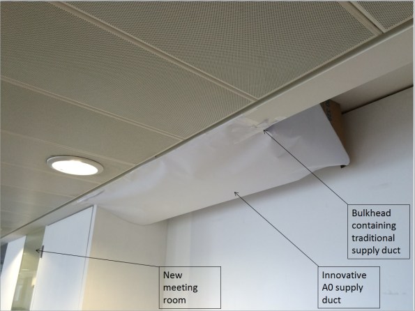
In other news George Garthwaite was born just under a month ago. I very nearly got to add midwifery to my competencies, but thankfully a professional arrived in the nick of time. Everyone is doing well. Thank you very much for the Giraffe and bibs from the Mess.

The art of communication
ICE Attribute 8 Interpersonal Skills and Communication. Obviously an important attribute towards being an effective engineer and ultimately chartering otherwise it wouldn’t be on the list. Going through the sequencing of the infamous starburst today I hit a bump in the road with a senior site manager. I thought I would share today’s experience to see if anyone else has had similar. This is what happened…..
Having actually paid attention to John and his picture method statements, sequencing, logical bite sized chunks of a single activity to communicate a plan in its simplest form, I decided to query part of the staging breakdown for the construction of the starburst. To read you in: we had Stage 2 – installing a temporary cantilevered deck, followed by Stage 3 – craning and installing screens to the temporary platform paired with the pouring of a concrete slab – completely unrelated tasks, completed by different subcontractors, and not done concurrently. Suggesting that the screens could potentially be a separate stage in itself nearly induced a heart attack; so the suggestion that stage 2 – the installation of 4 x 2.8m deep trusses topped with secondary steel and ply decking, may require breaking down a bit further didn’t fair much better; so I steered towards grouping the installation of the deck and screens together – done by the same subcontractor, both temporary works, both require the crane – seemed logical to me. Now, the actual sequence of works was not under debate, just the sequence breakdown into stages, which is ultimately how this will be communicated. For something that will be constructed 220m in the air, cantilevering 9+m off the superstructure, I think it’s important to remove any form of ambiguity and confusion. Putting two unrelated activities by different subcontractors into the same stage, I think, treads the line of ambiguity and confusion. Especially when the two people planning this thing, will not be there to see it constructed. This is at least what I told myself when I chose to challenge the plan and was shot down– or was it just a red flag to a bull when the response which finally ended the conversation after a bit of discussion, was ‘I’ve done this for over 20 years, I know what works, and this just works’? No further explanation required/offered. I’ve got my own answer to that question.
Maybe I need to work on my communication skills!
Obvious Mistake II
On the same vain as Rich; spot the obvious mistake in this budget E&M installation. It amuses me every day as I walk to work (whenever it rains).
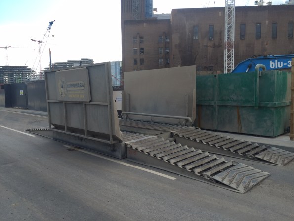
Spot the Obvious Mistake
Following on from my previous Blog Post: “A wheel wash – yes honestly the story of a wheel wash”. My exciting challenge to all bloggers is to spot the obvious error ( I hasten to add I am afraid this is not an interesting geotechnical issue).
Help – I am sorry I haven’t a clue
Pride cometh before a fall. I have been working on how to remove the temporary restraints from the secant pile wall for about a fortnight and now I am well and truly stuck. The waler and struts clash with 2 of the slabs. I have deduced 3 possible options, propping off the capping beam with hydraulic props, temporary propping from a lower basement (B3 to B2) and then cantilever the rest of the way, and the third is a hybrid of the two.
![IMG_2567[1]](https://pewpetblog.com/wp-content/uploads/2016/05/img_25671.jpg?w=595)
Some of the said struts and walers (they are 900 mm in diameter not including splice)
Time is of the essence here and the PM will not accept any loss of time. Which begs the question why didn’t he allow for their removal in the programme? I am naturally prejudiced against the cantilever option as because it slows the removal of the struts and walers by restricting access and I can’t help but ask why the didn’t do this before. The calculated delay to programme is 5 days. With LDs this works out to about $150,000 in lost time. The cost of hiring the temporary props is down to the sub-contractor so this isn’t much of a consideration. Risks – Removal of temp struts and the capacity of the capping beam is not yet known.
Option 2 (propping from B3-B2) is slightly quicker to remove the struts and walers with less temporary works but, it turns out both options require the pour 1 on B2 to be at strength before any struts can be removed so it still works out to a delay of 5 days. However, the wall is deformation is potentially worse and getting the necessary prestress into a diagonal prop can be very problematic.

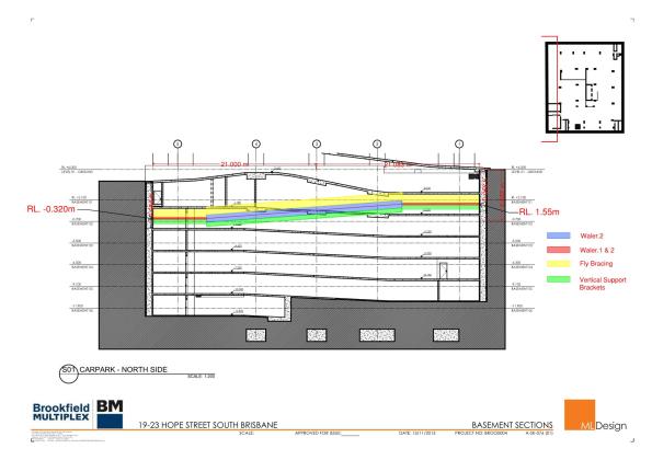
How the slabs work (numbers denote by pour a slab system is not locked until Pour 1 of the next basement level is at strength). The struts are located between B3 pour 4 and B2 pour 1.
Option 3 (Hybrid) has no delay to the programme but the most amount of temporary works (off critical path) – problem solved right? Wrong my PM has a ‘gut feeling’ and an inspirational idea. Just build over them! This might work if they were designed that way. While I and the Project Engineer were trying to argue for alternatives and pointing out how were we going to remove some of the members that are over 12 tonnes under ground in confined conditions without access to plant, I was being treated to a truly marvellous display of Oxford Union esque debating skills of “yeah I hear what you are saying but what my gut is telling me is if we build over it doesn’t cost me any time”. He then went on to show how we could encaste pulleys in the slab above (fiddling while Rome burned). I am starting to get an idea how this job was was so poorly priced and why it is so far behind programme.
To make matters worse he hasn’t paid Franki Pile who are the design authority for the wall and whose help we need to make this happen. As you can tell my meeting with Franki’s did not go well and I got my arse truly handed to me. While I need to man up and realise tomorrow is another day, other than quick strength concrete to gain the necessary 20 MPa quicker I am pretty much out of options or asking one of our drug dealer neighbours to bust a cap in the PM other than that I am pretty stuck. Do I swallow my pride, log everything and accept it will make a hell of a TMR?
More sketches to follow.
The nature of the problemthe struts cutting though pour 4 basement 2 (B2)and pour 1 basement 1 (B1).

The hashed areas are (temorary props option 2) the struts shown are the existing props. Option 1 would see them replaced by 2 props in each corner off the capping beam.
More heritage complications…
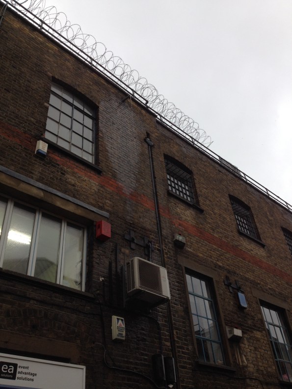
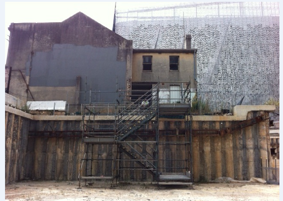
Consistent with my other blogs, this one also focuses on a heritage issue. Our structural design consultants have deemed the heritage building so unstable that much of it needs remediation before adjacent works can continue. Whilst there are many areas which require attention, this blog will focus on ‘The Southern Wall’. An elevation of the Southern Wall is shown in Figure 1. It is the wall without windows, half painted grey and it is a miracle the thing is still standing.
Figure 1.
Several methods of reinstating the structural integrity of the building have been investigated but due to the time it takes to gain permission to do almost anything inside a heritage building, the level of internal instability between floors, contractual complexities and more – a temporary external fix has been selected. The solution involves three levels of walers being attached to the wall and then braced by a series of props. The solution is illustrated in Figure 2 and Figure 3.
Figure 2.
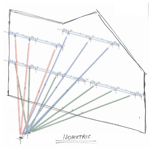
Figure 3.
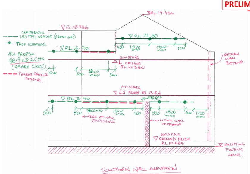
This solution minimises the impact on the programme and allows works in the vicinity to continue, largely uninterrupted. The lower most waler is supported by the green props which all converge on to a single brace plate (BP1). The brace plat is bolted to the existing capping beam, but has had to be drilled to slot over the starter bars. The other two walers are braced by two separate groups of props, all of which converge to a second, separate brace plate (BP2). See Figure 4 for detail. Connection details are illustrated in Figure 5.
Figure 4.
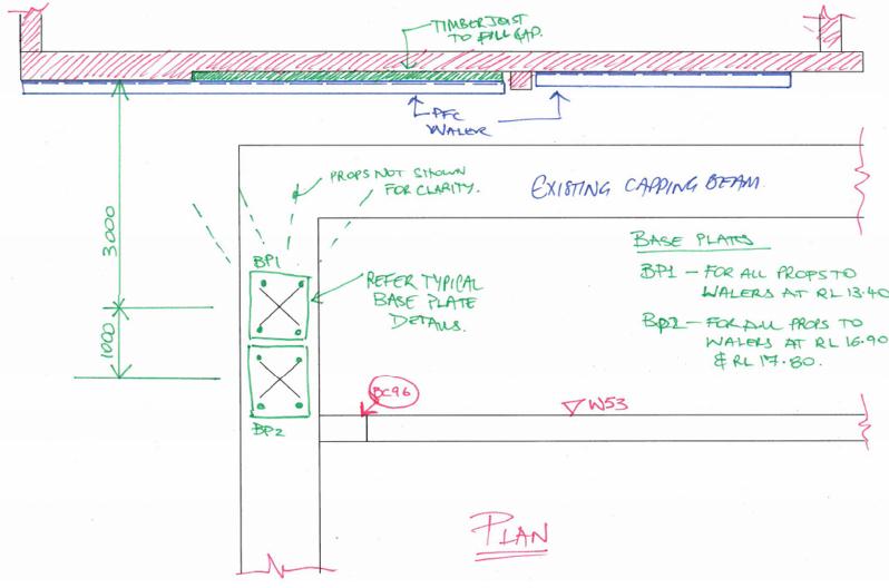
Figure 5.

Not only does the steel provide support in elevation, they also prevent the road side elevation from falling into the adjacent street. It is difficult, but possible to see in Figure 1 that the western most 1.8m of the building (the left hand side) is almost entirely separate from the rest of the structure. Existing internal braces go some way to remediate this problem, but the proposed solution will help to prevent the matter from getting worse.
The long term solution is expected to be in the form of timber frames which will be sandwiched between the ceilings and floors of the building. Due to the issues highlighted at the start of this blog, this long term solution will be tackled in the distant future. This temporary solution is due to be constructed this week, I will post photos once complete.
