Archive
Raystown Dam & Reservoir
Raystown
I was toying with a semi-technical blog, but then realised I hadn’t actually finished my “interesting things that USACE do that the Royal Engineers don’t do” mini-series. So here goes, today I’ll be looking at the Raystown dam and reservoir.
I visited the site a couple of weeks ago. This gave me the opportunity to tour the facilities, but seeing as it’s located 175 miles from Baltimore in the middle of deepest darkest Pennsylvania it also afforded a good excuse to do some walking and go camping for a night. It was also the piece of critical national infrastructure that the cadets had to go and ‘recon’ so it made sense to do backbriefs etc on-location.
Anyway, a bit of background: Construction began in 1968, and it was by most accounts quite unpopular at the time; the perceived wisdom being that all available funds should be used to support troops in Vietnam! Construction was completed in 1972, and the accompanying recreation area was inaugurated a couple of years later in 1974. The principal purpose of the dam was flood defence, with the creation of a recreation area a close second. Power generation wasn’t even considered at this stage, however a 21MW hydroelectric plant has subsequently been added. Interestingly this is the only part of the site (including wildlife management schemes) that isn’t directly administered by USACE. Immediately following construction, the area was hit by tropical storm Agnes, which all but filled the reservoir only months after completion. Had the dam not been built the Juniata (and subsequent valleys) would have experienced the worst flooding on record.

Raystown Earth Dam
Some facts and figures then: The principal dam is 69m high, with a planned ‘constant’ water depth of 58m at the deepest point by the dam. The dam itself is a classic earth (or embankment) dam with a clay core. Material for the dam was harvested nearby, in an area which now serves as the emergency spillway should the reservoir overfill and other mitigation measures fail. There is a secondary (much smaller) concrete dam which houses the main spillways and regulation gates. The hydroelectric plant has its own water feed and under normal operation all water leaving the reservoir passes through the plant. The spillway is only utilised when the volume of water in the reservoir becomes too great for the plant to handle on its own. The lake is approximately 45km long, has a 180km long shoreline, covers an area of 34km2, and has a flood capacity of around 306,000,000m3. Interestingly there is no ‘Raystown’ nearby. I asked about this, and the only answer I could get is that the project was named after a local trapper (presumably called Ray) of some fame from “the old days”!

Concrete Dam and Spillway
Some interesting engineering points came out of the facilities tour. During construction 5 massive movable steel bulkheads were created and ingeniously stored within the dam. The idea being that when required they could be hoisted out and dropped into position across the spillways allowing the main gates to be serviced. However, once lowered into position the designers failed to take into account the ergonomics of the finished dam. When it came to using them for the first time it became apparent that no crane could get close enough to lift them out because they are unable to deploy their spreaders sufficiently on the service road on the top of the dam. The bulkheads have thus sat undisturbed, entombed in the dam since 1971! Down at the bottom of the dam (below the lowest water level) there are a series of walls drains to reduce the pore-water pressures acting against the foot of the dam. There are also a series of “bubblers” which are simple air pipes used to pump air out from the bottom of the spillway entrance in order to circulate water and to try and prevent or reduce damage caused by water freezing in and around the spillway gates. There are three separate water inlets from three different depths within the reservoir. This allows the operator to take different proportions of water from different depths in order to mix them and achieve the desired temperature before releasing water downstream; an important environmental consideration.


Emergency Spillway Tower & Bubblers and Wall-drains (within the concrete dam)
The reservoir also has a ‘plughole’, or in this case a 9m x 6m tunnel which runs from the bottom of the original valley out into the river beyond the dam. It has never had to be utilised, but it is controlled from a giant tower which stands in the middle of the emergency spillway. During the tour we were able to go down and look at the giant pistons which operate the ‘plug’. Also of engineering interest is the emergency spillway. This appear to be just a giant field, however it has been engineered to have specific properties. The upper lip is bedrock which has been chiselled out of the hill in order to form a specific level below which the water will remain contained in the lake. Onto this however an earth bund has been installed which is approximately 1m high. This is made is made of ‘erodeable’ material which has been designed so that it will contain water up to a certain height, but that once breached it will be washed away emptying the lake down to the level of the bedrock lip. Simple but clever engineering.
During my visit, I had to keep reminding myself that the site was completely designed, built and managed by USACE, and that this represents one of many similar projects across the country. The reach and scope of the organisation is quite staggering, it really is a very different beast to our own military.
Other News
It looks like some of the QC contractors will be losing their jobs soon. Apparently it’s not okay to just turn up at meetings, make promises then not do anything. They have two weeks to turn it all around but it’s not looking good! More to follow. Finally, bacon covered doughnut anyone?………….

What do you do when you pour the wrong concrete?
Well, apparently nothing. A recent issue we have had at the NLE involves a situation where we “accidentally” poured the wrong concrete. Of course there were processes in place that should have prevented this but it still happened.
The pour in question was for a 2m x 2m section of capping beam 8m long. The design requires a C50/60 concrete strength (C50/60 20mm CIIIA+SR DC-3). Unfortunately the last 13m3 poured was a C32/40 20mm CIIIIA WRA Pump Mix (a Temporary Works concrete mix). Not great for the 150 year life span required by the client.
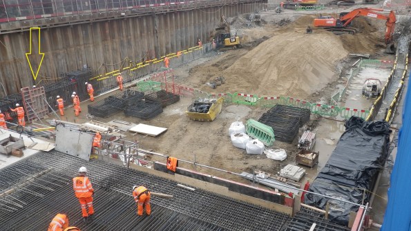
Pour 5 – South side of Capping Beam (yellow arrow)
This particular section started pouring at 1715 (a slab was also poured earlier in the day). And whilst the concrete was only just going warm and the pump was still being cleaned out the site engineer at 8pm then realised the issue. The fact that almost the entire workforce had already left the immediate call was to leave it in. The next morning, once we understood the full picture, again the decision was made to leave it in. Of course if you are going to strip it out you want to do that as soon as possible before the concrete gains any significant strength. So what was the perfect storm that led to this problem happening in the first place?
Supply
The concrete is being supplied by London Concrete, and although only one mix was ordered that day the supplier changed the mix after 8 loads (62m3) for the last 2 loads (13m3). London Concretes reason for this is that a computer crash required the staff to re-input the mix design which they got wrong. Crucially the delivery ticket did show C32/40 mix.
Checking
The site if using a sub-contractor (ESG) to conduct testing of concrete. Flow tests are taken on every load and cubes every 50m3. Incidentally they are meant to also check the mix design. The C50/60 concrete is designed to have a 600mm flow where as the C32/40 concrete is a much stiffer mix and designed to have a 170mm slump. When tested the C32/40 mix achieved 560mm flow! – so the load passed and was accepted. Quite luckily 4 cubes were taken for this load.
Pre-pour checks
Finally the site engineers are meant to check the delivery tickets, test and accept the load. Whilst they do this they fill out a pre-pour inspection sheet. Unfortunately the practice that has crept in is that the Site Engineers collect the tickets and fill out the inspection sheet later after the pour in the office. Incidentally no one noticed the difference in mix when it was loaded into the pump or when it was placed.


Resolution
Well, once the decision was made not to strip it out early you might as well leave it and see how it goes. 7 day cubes achieved 35kN/m2 so we are pretty confident that the final strength will achieve at least 40kN/m2.
Removal – If we were to remove the offending concrete (about 0.65m from the top) we would need to hydro-dem it off. High pressure water jet that strips concrete (queue much YouTube video research on what this entailed). This is apparently very cool and efficient but expensive and requires a lot of measures to protect people from flying concrete. The estimated cost came in at £200,000 to go down this avenue (not including the cost of additional concrete which would have been negligible in comparison). As the project Manager said “I would rather have to paint the beam in gold than have to strip it out”.
Re-analysis – The principle designers were good and very quick at giving their assessment within hours of being told the next morning. Their assessment is that a reduction in concrete strength reduces the bending capacity, bond strength and shear capacity. The bond strength is the most significant. However in another stroke of luck we changed the top and bottom laps to couplers to assist the construction programme which laps only in the side reinforcement. A review of the beam calculated as if it was all C32/40 and it showed that the section had adequate capacity.
The only concern Motts has is over the durability, the C32/40 design mix complies with DC-2 chemical class where as DC-1 is required. This means that we need to ensure that our backfill material is tested for sulphate content – this is an easy fix.(having had a look though Eurocode 2, I can’t see any reference to DC chemical classes. I will ask next time I see Motts but does anyone know where this reference comes from?)
Outcome
London underground have now officially received this information during a joint client/contractor/designer meeting yesterday and they are reviewing. Hopefully they should accept it but they are within their rights to ask for it to be replaced. This is a target price contract (50:50) but being a defect the cost would fall all on FLO.
In chatting with the structural engineering team they say that the reduction on concrete grade has little effect on the section capacity. I am not sure on the loads but I certainly remember quite a high sensitivity of concrete strength on the capacity of a section. Which implies that there is plenty of “fat” in the design. Additionally the impact I have noticed with the operatives is the impression that mistakes like this are ok to make which really is the wrong message. We have amended the processes on site. It was a close call which we just got away with. Had circumstances been slightly differently, we might be coating the beam in gold!
