Project Update: A Relentless Pursuit for Cost, Quality and Time
Now TMR1 and Thesis Form A’s are out the way I thought I’d provide an update on placement progress and a few of the issues we have encountered along the way. As my title suggests many of these are occuring because of the relentless pressure on the construction team to deliver the project as quickly, cheaply and to uncompromisingly high quality . As we know from phase 1 something probably should be prioritised, unfortunately that doesn’t appear to be a well received strategy on site.
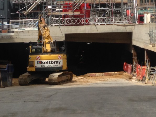
As you may recall (probably not) from my first blog we are using a top down methodology on the main Tower structure. Underneath the large Ground Floor (GF)slab we have unleashed the earth work contractors to crack on with the bulk excavation, taking our basement level from 9.0m OD to around 2.0m OD at its greatest point. This is a twelve week programme based on a target of moving 100 spoil vehicles away from site each day. The largest obstacle to this operation is not the digging or site movement of spoil, it is actually getting enough vehicles to and from site despite the constant challenge of breaking through London traffic. As such much of the earth is moved away at night which is probably proving a delight to our few local residents. To the sub-contractors credit they are doing well; they have their own exclusion zone so everyone else is able to keep out the way, which is useful considering the large number of excavators and dump trucks rattling around below our feet. Now they are underway tempo is impressively frenetic and as a result the ‘Bat Cave’ is taking shape nicely.
![IMG_0246[1]](https://pewpetblog.com/wp-content/uploads/2016/06/img_02461.jpg?w=595)
![IMG_0241[1]](https://pewpetblog.com/wp-content/uploads/2016/06/img_02411.jpg?w=595) The challenge of starting this process did throw up a nice on site leadership issue. After four weeks of hard work thrashing themselves to get the basement ready for commencement of this excavation , which they achieved, the junior construction team got a harsh email from a senior manager criticising quite a few trivial things on site. This inspired a near mutiny and, for a few days, a very inharmonious working environment. It was remedied by an honest, open conversation between various levels of management. One of the junior managers (not me I should add) fluctuated between near tears and incandescent rage when explaining his disapproval of the heavy criticism the on-site construction team was consistently receiving from, in his words, ‘Office bound desk jockeys’. Add a few favourite Aussie expletives in there behind the word jockey and you get the gist of his point. Everyone is now friends again, for the moment, but the unrelenting pressure applied by the project management team is starting to take its toll on morale. We shall see how long the current truce lasts.
The challenge of starting this process did throw up a nice on site leadership issue. After four weeks of hard work thrashing themselves to get the basement ready for commencement of this excavation , which they achieved, the junior construction team got a harsh email from a senior manager criticising quite a few trivial things on site. This inspired a near mutiny and, for a few days, a very inharmonious working environment. It was remedied by an honest, open conversation between various levels of management. One of the junior managers (not me I should add) fluctuated between near tears and incandescent rage when explaining his disapproval of the heavy criticism the on-site construction team was consistently receiving from, in his words, ‘Office bound desk jockeys’. Add a few favourite Aussie expletives in there behind the word jockey and you get the gist of his point. Everyone is now friends again, for the moment, but the unrelenting pressure applied by the project management team is starting to take its toll on morale. We shall see how long the current truce lasts.
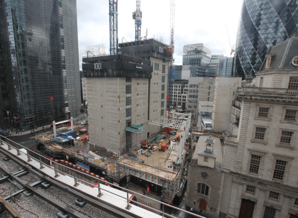
Above the GF slab we have commenced structural steelwork on the main Tower, another key milestone. On Saturday six 20 Tonne steel columns were erected with a mobile crane. This was all going well until they realised that the lifting plates, temporary steel lifting connections attached to the head of each column, were fabricated in the wrong orientation. Fortunately, with use of a heavy duty steel drill and an extra few hours the issue got fixed and the columns were placed upright in the correct position. Drilling extra holes into precision fabricated steel elements on site isn’t an elegant solution but it worked. Now the columns are in place steel beams are starting to fly in (not literally of course) and the skeleton of the ground floor structure is rapidly taking shape. The steel erection is surprisingly quick and they are clearly a well-rehearsed team. Floor one will hopefully be complete in a few weeks, at which point we will have only 39 more storeys to go!


Above the steelwork the east slip form rig of the large central concrete core has begun to rise once again. Its currently at floor 8 and will pause at a pre-determined hold point on floor 10, allowing the western component of this core to catch up. We will not be able to progress the core beyond floor 10 until the pile cap is constructed in the basement. This controls the vertical load through the exposed plunge columns in the basement, primarily required to prevent them buckling which is obviously bad when you have 10 storey’s of reinforced concrete suspended on them. Once the pile cap is constructed the effective length of these columns is gradually reduced which allows us to increase the axial loads and continue the progress of the slip form.
We have also increased the Tower Cranes on site from 1 to 3. To make things more challenging we selected self-climbing cranes, one suspended inside each core. These effectively hang off the walls of the cores and climb up the lift shafts behind the slip form rig. Unfortunately this is reasonably new technology in the UK and nobody really understands the process for each climb or how long it will take. We really are making much of it up as we go along. What we do know is that if we don’t figure it out soon then the slip form rig will catch up with and hit the crane. This is problematic. The other excellent news is that our three cranes are all pretty much aligned on the same axis and therefore clash frequently. Trying to figure out which crane can do which task without impeding other works is like a giant Crystal Maze puzzle with no solution. This problem has an impressive number of intelligent people very confused for most hours of the day.

And in final news we had a very serious accident on site. A scaffold contractor fell roughly seven metres through a hole in the GF slab and into the basement excavation. I’m told that’s far enough to know you are falling before hitting the ground, which is obviously a long way. The investigation is ongoing so I can’t really add anything else other than that his injuries are, luckily, fairly minor considering the distance he fell. He landed on soft, loose soil which was very fortunate indeed. Had he hit the large item of plant located close by it probably would have been a different outcome. Without going into the details it looks like a freak accident, that said it proves the point that if something can go wrong, give it enough time and it probably will. Be careful out there folks!
In summary, tempo is relentless in order to maintain programme, quality cannot be compromised and the cost must be controlled. This all adds up to a very challenging construction project with lots at stake. More to follow once the excavation hits the pile cap OD.

Tom,
I am impressed you can remove spoil overnight. Where is it going as most receiving sites presumably do not open through the night. Then again perhaps I was deceived by Erith!
Climbing tower cranes. How have the shear walls been adapted to carry additional moment?
Your basement plunge columns – how did the piles get formed to a low level (cased) or did the pile have to get broken down?
Is this new pile cap going in at formation level or raised up? If formation level how does it reduce the effective length, is it due to fixity?
How are noise, dust emissions controlled in top down construction?
Tom, can you expand on what you mean by not understanding the climbing process – do you mean the physical process of climbing the crane, or the sequencing with other works?
Jo,
People keep telling me this system has never really been used in the UK before so the first problem is that we have no one on site with past experience of its installation or operation.
Ideally you would just press a button and the thing would rise on automated hydraulic jacks but unfortunately that’s not the case. The crane installation team need to get at the chocking frames to conduct more welding. This means that a. These people need safe access which requires scaffold all the way up the core below them and b. Components for this work need dropping into position as they can’t be carried up. This means we are trying to drop large steel sections through gaps in an operational slip form rig and down a lift shaft which is already conjested with the crane tower sections. To do this we also need to make ammendmnets to the trailing deck of the slip form rig which adds further time to the process.
In the design stage they projected a climb would take 6 hours to complete. The crane specialists are now telling us they need 3 days. This is not good when you have already contracturally oversubscribed your limited crane capacity. Sub-contractors are not happy.
We also don’t know how often we need to climb the crane. Doing it regularly reduces risk of clashes with the slip form rig but increases the hours the crane is out of operation.
The reality is that we will probably learn some tedious lessons on the first climb which will improve the process for the rest of the project. As we are likely to climb each crane about 15 times over the next two years you’d hope we get good at it.
Tom, self climbing cranes are the crane of choice over here. I’m sitting down with the senior site manager tomorrow morning to discuss various bits and pieces and he’s been promising me a discussion on the cranes for a little while now so I’ll pin him down on that subject and see how we are managing these issues. Appreciate that its relatively unused in the UK, but surely BM is not adverse to picking the brains of their international peers when someone else has more in depth knowledge about a subject rather than working something out from scratch? I do know that it is anticipated to take 4 hrs to jump our crane – where in the world does 3 days come from??!!!! How many levels will there be between the slip form and the crane grillage, and how many levels do you trailing decks go down?
Damo,
The Tower crane is suspended on chocking frames which are held in place using large beams that extend into pre cast voids in the concrete core walls. These voids are placed regularly up the length of the wall and are formed as the slip form rig progresses, much in the same manner as embedment plates or architectural voids such as lift shaft openings. Extra reiforcement bar is installed around these openings but as I understand it the crane load is mainly carried in shear. I’ll try to do a subsequent blog on this system once I understand it a bit better.
The piles were formed long before my arrival but the generic process for the main plunge columns is as follows:
1. Install pile encasement to clay layer
2. Bore through encasement to toe depth
3. Bentonite used to stabilise lower levels of pile (around -48m OD)
3. Emplace internal tremmie pipes
4. Concrete pumped into shaft up to pile cap OD.
5. Plunge columns almost immediately suspended through tremmie pipes and into the wet concrete, levelled and positioned before concrete has sufficiently cured.
6. Concrete gains strength retaining plunge columns in position.
7. Tremmie pipes and encasement removed and piles backfilled between concrete level and surface.
On one of the piles the plunge column was positioned incorrectly (by 30mm) and by the time the engineers realised the concrete had started to cure without the plunge column correctly installed. Once this occured the only way to resolve the issue was to construct a cofferdam to isolate the pile, excavate to the concrete pile depth, break out the concrete and connect the plunge column with a independent pile cap. For a 30mm inacuracy this cost a lot of money and time to fix!
As a result of this method we are not breaking out concrete as we go. The excavation process exposes (very carefully I should add) the steel plunge columns as depth is increased.
Ref the plunge column loading:
The pile cap, once constructed will be 3.0m of reinforced concrete. The worst condition in terms of length for each of these steel columns occurs when the base of the pile cap is exposed. The effective length (Leff) at this point goes from around 10m OD to 0.3m OD. Once the pile cap and BL2 slab is poured the Leff reduces by 3.0m. When the BL1 slab is then constructed at 9.25m OD (450mm slab) it provides lateral restraint to the columns which further reduce the Leff to approximately 5.5m. These stages allow us to increase axial load with further tower construction.
Noise and dust is clearly a problem though because it is all hidden away within a giant concrete box it appears to be acceptable. The majority of noisy works, such as internal excavations are done during the day. The only machine operating at night is the excavator loading the tipper trucks from the stock pile. Plus we are right in the city so, though they exist, local residents loosing sleep at nighty are fortunately few and far between.
Thanks Tom,
To return to a couple of the questions: 1) Are the muck away vehicles a complete fleet or is there a turn around over night i.e. are they able to use receiving site overnight? 2) noise and dust, although ‘hidden away’, are controlled differently for on site operatives as opposed to the general public adjacent to the site. What monitoring is being employed and how is duty of care being exercised? Do you have view on this and/or influence?
Rich,
The sub-contractors responsible for the excavation operation have vehicles running almost 24hrs a day at the moment and have therefore hired in additional vehicles to assist the removal of earth material. The only time they don’t move into site is during rush hour periods. Noise on our site boundary is monitored regularly though we have not exceeded the permissible limit to date. Other than ensuring the particularly nosiy site tasks, such as breaking out concrete or operation of heavy machinery, are not completed during night works, mitgiation measures are relatively limited. At this point this strategy is sufficient and we have not recieved any complaints. The main contractor is generally very good at appeasing the local population and keeping them well informed so relationship with the community is currently very positive. Management are keen to keep it that way so minimising disruption, particularly during night hours, is a high priority for all trades working on site.
Tom – Many thanks for the reply. Just to come back on a couple of things – where do the muck away lorries off-load their spoil. Is there a receiving site open 24hrs too?
Are you going to have to brace any of the plunge columns to prevent buckling when the maximum effective length is reached?
Damo,
I’m told the muck away lorries go to either Rainham or Dagenham. One of these centres is being paid to recieve spoil 24hrs a day. The manager in charge of the excavation also told me that the excavation contractors have a side buisness conducting large scale landscaping projects such as golf courses etc. This could be a joke but it would make a sensible place to hide loads of spoil!
There is no bracing required to restrain these columns because the worst case load condition in the short term condition has been quite accurately calculated. We know the size and loads of the core, the slipform rig, cranes and personnel contributing to these loads quite accurately at each stage of the structure so there is very little chance that we could overload the columns beyond design capacity. Interestingly the designers stuck a 1.35 FoS onto this design as well. The senior Engr in the office thinks this is excessive because of the short term nature of the loading on the columns and becuase we have a high degree of control on the loading of these columns.
As a result, the engineer consultants are quite confident we could rise our cores and increase the loading by a few more floors before the risk of the columns buckling became a worrysome issue.
It would be interesting to see how this FoS and the Engineer Consultants design methodology would hold up against pressures from the main contractor should we get behind schedule and seek additional programme efficiencies. I wouldnt be surprised if that FoS was reduced to allow more load to be applied earlier in the case that it would provide cost and time savings in the long run.
Tom,
Thanks for that. I could well believe that Rainham receives around the clock for a price!
I have worked for a middle man to provide access off the A3 to facilitate construction of a large sound bund and ‘nature scape’ that took a significant amount of imported engineering fill material aka muck-away so I am not at all surprised that the practice still exists although I am surprised that it is admitted to.
The FoS accounts for a large number of unknowns, which it would be no bad thing to list out ready for the day that pressure is brought to bear. Ultimately it is a statistical risk management tool that the insurers would need to price very carefully.
Tom great blog, how many basements levels do you have? Is there a limit to how far you can go down. I would assume that the to,era ce of the plunge columns would take effect at some point? I only ask ask as my site is crying out for a top down approach but there is nearly no spare room. I sympathise about the load out, how many cubes are you taking out a day?
Doug,
Technically there are 3 basement levels but one is an atrium that hangs from the GF slab. In simple terms we have two major slabs below ground level that perform a significant structural propping function.
Top down is a nice concept but it creates some absurd challenges as well. Most people here would probably prefer a traditional methodology on this project. The biggest poblem is that this method enables us to have concrete contractors, steel erectors and the excavation team working concurrently. Our site is also constrained so everyone is fighting over very limited space. Though this is good for the prgramme it makes the logistics and coordination a nightmare, which then starts to impact the contract terms.
Tom a good blog has attracted good discussion
I think that there are a couple of items to clarify in your profession review report
1 The hold point at 10 stories, is I think a consequence of the fact that the entire main core is suspended on a set of plunge columns , with the basement core being completed once there is access to the basement formation level – am I correct? This is pretty spectacular and I would like a photo of it.
2 As usual in jobs like this there is a pinch point on the vertical travel – ie the pressure for cranage always causes pinch points
3 It looks like some (all?) of the cranes are being moved up on frames inside the cores . You’d normally see this on the outside of the core and the jump would be effected in a half a day or so – any reason for the crane frames being inside the cores?
John,
Correct, the plunge columns are the only structural element transfering the vertical load from the reinforced concrete core to the load bearing piles currently buried below the excavation depth. In the worst condition the maximum unrestrained length of these columns, once fully exposed, will be 9.7m. This is when the pile cap is excavated but not cast with reinforced concrete. The design limits the loading at this point to ensure the columns do not buckle. As the pile cap is cast a 3m length of these columns will be encased and restrained, reducing the effective length by the same amount. As a result we can then increase the axial loading in these columns still further. Once BL2 and BL1 slabs are cast the columns are further restrained, allowing even more superstructure to be constructed and further load applied. As a result the hold points on the tower above ground floor are directly affected by the progress of the top down construction sequence of the basement.
Our two internal self climbing cranes do not have traditional foundations. Due to the top down methodology employed we can’t access pile foundations at this stage of the project. We could have technically used deep cofferdams but this would have been very expensive and would have obstructed much of our site. As a result the only way to provide the cranage required was to use the concrete core walls to suspend the cranes. Therefore placing them in a lift riser allows use of the reinforced concrete walls of the core for stability and load bearing.
These cranes sit on heavy steel chocking frames which are fixed against the core walls. Imagine climbing up inside a chimney breast by pushing your arms and legs out against opposite walls. It works in a similar way but we use heavy steel beams placed in wall voids to transfer the load from the chocking frame to the walls. From there the load goes down through the plunge columns and into the deep piles.
As a quick answer, the cranes are inside the cores becuase of the decision to use the top down methodology. Though this saves about 3 months off the programme by allowing construction of the superstructure and excavation concurrently it has caused immeasurable contructability issues on site.
Tom an excellent blog with some very interesting issues. Keep us up to date about the accident
Kind regards
Neil