Help – I am sorry I haven’t a clue
Pride cometh before a fall. I have been working on how to remove the temporary restraints from the secant pile wall for about a fortnight and now I am well and truly stuck. The waler and struts clash with 2 of the slabs. I have deduced 3 possible options, propping off the capping beam with hydraulic props, temporary propping from a lower basement (B3 to B2) and then cantilever the rest of the way, and the third is a hybrid of the two.
![IMG_2567[1]](https://pewpetblog.com/wp-content/uploads/2016/05/img_25671.jpg?w=595)
Some of the said struts and walers (they are 900 mm in diameter not including splice)
Time is of the essence here and the PM will not accept any loss of time. Which begs the question why didn’t he allow for their removal in the programme? I am naturally prejudiced against the cantilever option as because it slows the removal of the struts and walers by restricting access and I can’t help but ask why the didn’t do this before. The calculated delay to programme is 5 days. With LDs this works out to about $150,000 in lost time. The cost of hiring the temporary props is down to the sub-contractor so this isn’t much of a consideration. Risks – Removal of temp struts and the capacity of the capping beam is not yet known.
Option 2 (propping from B3-B2) is slightly quicker to remove the struts and walers with less temporary works but, it turns out both options require the pour 1 on B2 to be at strength before any struts can be removed so it still works out to a delay of 5 days. However, the wall is deformation is potentially worse and getting the necessary prestress into a diagonal prop can be very problematic.

How the slabs work (numbers denote by pour a slab system is not locked until Pour 1 of the next basement level is at strength). The struts are located between B3 pour 4 and B2 pour 1.
Option 3 (Hybrid) has no delay to the programme but the most amount of temporary works (off critical path) – problem solved right? Wrong my PM has a ‘gut feeling’ and an inspirational idea. Just build over them! This might work if they were designed that way. While I and the Project Engineer were trying to argue for alternatives and pointing out how were we going to remove some of the members that are over 12 tonnes under ground in confined conditions without access to plant, I was being treated to a truly marvellous display of Oxford Union esque debating skills of “yeah I hear what you are saying but what my gut is telling me is if we build over it doesn’t cost me any time”. He then went on to show how we could encaste pulleys in the slab above (fiddling while Rome burned). I am starting to get an idea how this job was was so poorly priced and why it is so far behind programme.
To make matters worse he hasn’t paid Franki Pile who are the design authority for the wall and whose help we need to make this happen. As you can tell my meeting with Franki’s did not go well and I got my arse truly handed to me. While I need to man up and realise tomorrow is another day, other than quick strength concrete to gain the necessary 20 MPa quicker I am pretty much out of options or asking one of our drug dealer neighbours to bust a cap in the PM other than that I am pretty stuck. Do I swallow my pride, log everything and accept it will make a hell of a TMR?
More sketches to follow.
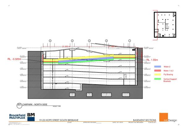
The nature of the problemthe struts cutting though pour 4 basement 2 (B2)and pour 1 basement 1 (B1).

The hashed areas are (temorary props option 2) the struts shown are the existing props. Option 1 would see them replaced by 2 props in each corner off the capping beam.

I would follow the PM instructions, document everything and start preparing to take over his job when it all goes to hell in a handcart.
I don’t think that would happen and I wouldn’t want it to. There are a lot of people ahead of me for the job.
Doug, on the top photo, level B1 is at propping level? Is B2 at the dredge level as shown and the B3 level to be dug a further level down?
How have you been trying to resolve this problem? Have you created your own engineering model (WALLAP) or otherwise? What are the assumptions you have made – such as serviceability limits of deflection into site. What are the problems with vertical deformation at ground level. I can see a building in the photos but what about on the other sides of the excavation.
Perhaps a review of the design approach to see where conservatisms were might help scale back some onerous factors of safety. Are you doing any monitoring – have you observed more or less than expected at this stage?
I am certain your corner props could come out now without any issues but not sure that helps hugely.
Your suggestions on raking props and cantilvering sound interesting (and not too unusual).
Other thoughts
– have you considered ground anchors(!)
– Why can you not cast slabs in such a way to reduce deflections of the temporary props and enable their release?
Damian,
I am coming back up from basement level 6 and have 3 rows of ground anchors that I finished last week.
Ground Anchors Solution- The reason why we propped here in the first place is the neighbours basement.
For neighbouring buidings please see my first blog.
Why would I build my own WALLAP model when my PM is a carpenter without any formal training and doesn’t want to carry any engineering risk. I have used DPL to come up with loads.
Slab design – they don’t want any other changes as it will effect services.
I am doing monitoring. – it is less in most areas. current max delflection is 26 mm Thrshold is 39 mm.
Doug
Who said that the attachments were supposed to be easy, especially when you have no support or common sense from above. What happened to teamwork? I must admit that I am slightly confused as to the options.
All the best
Kind regards
Neil
Doug,
Looks fun but like Neil I am struggling to understand the full detail of the problem and the mitigation options available to you. This might help or it might not but on our site we have a substantial corner prop located below our cast GF slab. I asked how we intend to remove it without lifting access from a Tower Crane and the contractors briefed me on an elaborate scheme using either chains on a pulley system or genie lifts. Apparently this will allow us to lower the propping once it is no longer required.
Tom, it is actually quite difficult to explain without a lot of slides. It’s a 3 dimensional problem that a lot of people are struggling with. I have a solution – the hybrid solution of props off the capping beam and then takes props from B3 to B2 (option 1 and 2). This is a bottom up construction the struts and walers are enormous and cannot be removed until the system is locked in with the pour of B1 in or some form of propping system. We cannot lose any time so it’s the hybrid or build over. Build over will keep the project going on paper but, will screw the job up and probably lead to a union walkout. One of the struts goes through pour 4 and pour 1 of the next floor. What I need to demonstrate is that in building over productivity and safety will drop through the floor.
Ok update, I have met with the Project Engineer, the site manager and the union rep and we are fully on one song sheet and have spent the day figuring how much building over would delay the project which is the key to winning the argument (I think). I will let you m so how this goes. Damo to make you happy I have done the home made Wallap analysis and the load off the capping beam is in the region of 118 Kn/m off the capping beam from B3.
How did this all pan out? Did sense and reason win the day or have you installed blocks and pulleys in the slab?