Archive
Raystown Dam & Reservoir
Raystown
I was toying with a semi-technical blog, but then realised I hadn’t actually finished my “interesting things that USACE do that the Royal Engineers don’t do” mini-series. So here goes, today I’ll be looking at the Raystown dam and reservoir.
I visited the site a couple of weeks ago. This gave me the opportunity to tour the facilities, but seeing as it’s located 175 miles from Baltimore in the middle of deepest darkest Pennsylvania it also afforded a good excuse to do some walking and go camping for a night. It was also the piece of critical national infrastructure that the cadets had to go and ‘recon’ so it made sense to do backbriefs etc on-location.
Anyway, a bit of background: Construction began in 1968, and it was by most accounts quite unpopular at the time; the perceived wisdom being that all available funds should be used to support troops in Vietnam! Construction was completed in 1972, and the accompanying recreation area was inaugurated a couple of years later in 1974. The principal purpose of the dam was flood defence, with the creation of a recreation area a close second. Power generation wasn’t even considered at this stage, however a 21MW hydroelectric plant has subsequently been added. Interestingly this is the only part of the site (including wildlife management schemes) that isn’t directly administered by USACE. Immediately following construction, the area was hit by tropical storm Agnes, which all but filled the reservoir only months after completion. Had the dam not been built the Juniata (and subsequent valleys) would have experienced the worst flooding on record.

Raystown Earth Dam
Some facts and figures then: The principal dam is 69m high, with a planned ‘constant’ water depth of 58m at the deepest point by the dam. The dam itself is a classic earth (or embankment) dam with a clay core. Material for the dam was harvested nearby, in an area which now serves as the emergency spillway should the reservoir overfill and other mitigation measures fail. There is a secondary (much smaller) concrete dam which houses the main spillways and regulation gates. The hydroelectric plant has its own water feed and under normal operation all water leaving the reservoir passes through the plant. The spillway is only utilised when the volume of water in the reservoir becomes too great for the plant to handle on its own. The lake is approximately 45km long, has a 180km long shoreline, covers an area of 34km2, and has a flood capacity of around 306,000,000m3. Interestingly there is no ‘Raystown’ nearby. I asked about this, and the only answer I could get is that the project was named after a local trapper (presumably called Ray) of some fame from “the old days”!

Concrete Dam and Spillway
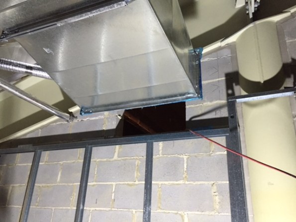
Some interesting engineering points came out of the facilities tour. During construction 5 massive movable steel bulkheads were created and ingeniously stored within the dam. The idea being that when required they could be hoisted out and dropped into position across the spillways allowing the main gates to be serviced. However, once lowered into position the designers failed to take into account the ergonomics of the finished dam. When it came to using them for the first time it became apparent that no crane could get close enough to lift them out because they are unable to deploy their spreaders sufficiently on the service road on the top of the dam. The bulkheads have thus sat undisturbed, entombed in the dam since 1971! Down at the bottom of the dam (below the lowest water level) there are a series of walls drains to reduce the pore-water pressures acting against the foot of the dam. There are also a series of “bubblers” which are simple air pipes used to pump air out from the bottom of the spillway entrance in order to circulate water and to try and prevent or reduce damage caused by water freezing in and around the spillway gates. There are three separate water inlets from three different depths within the reservoir. This allows the operator to take different proportions of water from different depths in order to mix them and achieve the desired temperature before releasing water downstream; an important environmental consideration.


Emergency Spillway Tower & Bubblers and Wall-drains (within the concrete dam)
The reservoir also has a ‘plughole’, or in this case a 9m x 6m tunnel which runs from the bottom of the original valley out into the river beyond the dam. It has never had to be utilised, but it is controlled from a giant tower which stands in the middle of the emergency spillway. During the tour we were able to go down and look at the giant pistons which operate the ‘plug’. Also of engineering interest is the emergency spillway. This appear to be just a giant field, however it has been engineered to have specific properties. The upper lip is bedrock which has been chiselled out of the hill in order to form a specific level below which the water will remain contained in the lake. Onto this however an earth bund has been installed which is approximately 1m high. This is made is made of ‘erodeable’ material which has been designed so that it will contain water up to a certain height, but that once breached it will be washed away emptying the lake down to the level of the bedrock lip. Simple but clever engineering.
During my visit, I had to keep reminding myself that the site was completely designed, built and managed by USACE, and that this represents one of many similar projects across the country. The reach and scope of the organisation is quite staggering, it really is a very different beast to our own military.
Other News
It looks like some of the QC contractors will be losing their jobs soon. Apparently it’s not okay to just turn up at meetings, make promises then not do anything. They have two weeks to turn it all around but it’s not looking good! More to follow. Finally, bacon covered doughnut anyone?………….

What do you do when you pour the wrong concrete?
Well, apparently nothing. A recent issue we have had at the NLE involves a situation where we “accidentally” poured the wrong concrete. Of course there were processes in place that should have prevented this but it still happened.
The pour in question was for a 2m x 2m section of capping beam 8m long. The design requires a C50/60 concrete strength (C50/60 20mm CIIIA+SR DC-3). Unfortunately the last 13m3 poured was a C32/40 20mm CIIIIA WRA Pump Mix (a Temporary Works concrete mix). Not great for the 150 year life span required by the client.
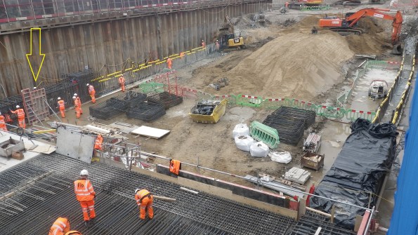
Pour 5 – South side of Capping Beam (yellow arrow)
This particular section started pouring at 1715 (a slab was also poured earlier in the day). And whilst the concrete was only just going warm and the pump was still being cleaned out the site engineer at 8pm then realised the issue. The fact that almost the entire workforce had already left the immediate call was to leave it in. The next morning, once we understood the full picture, again the decision was made to leave it in. Of course if you are going to strip it out you want to do that as soon as possible before the concrete gains any significant strength. So what was the perfect storm that led to this problem happening in the first place?
Supply
The concrete is being supplied by London Concrete, and although only one mix was ordered that day the supplier changed the mix after 8 loads (62m3) for the last 2 loads (13m3). London Concretes reason for this is that a computer crash required the staff to re-input the mix design which they got wrong. Crucially the delivery ticket did show C32/40 mix.
Checking
The site if using a sub-contractor (ESG) to conduct testing of concrete. Flow tests are taken on every load and cubes every 50m3. Incidentally they are meant to also check the mix design. The C50/60 concrete is designed to have a 600mm flow where as the C32/40 concrete is a much stiffer mix and designed to have a 170mm slump. When tested the C32/40 mix achieved 560mm flow! – so the load passed and was accepted. Quite luckily 4 cubes were taken for this load.
Pre-pour checks
Finally the site engineers are meant to check the delivery tickets, test and accept the load. Whilst they do this they fill out a pre-pour inspection sheet. Unfortunately the practice that has crept in is that the Site Engineers collect the tickets and fill out the inspection sheet later after the pour in the office. Incidentally no one noticed the difference in mix when it was loaded into the pump or when it was placed.


Resolution
Well, once the decision was made not to strip it out early you might as well leave it and see how it goes. 7 day cubes achieved 35kN/m2 so we are pretty confident that the final strength will achieve at least 40kN/m2.
Removal – If we were to remove the offending concrete (about 0.65m from the top) we would need to hydro-dem it off. High pressure water jet that strips concrete (queue much YouTube video research on what this entailed). This is apparently very cool and efficient but expensive and requires a lot of measures to protect people from flying concrete. The estimated cost came in at £200,000 to go down this avenue (not including the cost of additional concrete which would have been negligible in comparison). As the project Manager said “I would rather have to paint the beam in gold than have to strip it out”.
Re-analysis – The principle designers were good and very quick at giving their assessment within hours of being told the next morning. Their assessment is that a reduction in concrete strength reduces the bending capacity, bond strength and shear capacity. The bond strength is the most significant. However in another stroke of luck we changed the top and bottom laps to couplers to assist the construction programme which laps only in the side reinforcement. A review of the beam calculated as if it was all C32/40 and it showed that the section had adequate capacity.
The only concern Motts has is over the durability, the C32/40 design mix complies with DC-2 chemical class where as DC-1 is required. This means that we need to ensure that our backfill material is tested for sulphate content – this is an easy fix.(having had a look though Eurocode 2, I can’t see any reference to DC chemical classes. I will ask next time I see Motts but does anyone know where this reference comes from?)
Outcome
London underground have now officially received this information during a joint client/contractor/designer meeting yesterday and they are reviewing. Hopefully they should accept it but they are within their rights to ask for it to be replaced. This is a target price contract (50:50) but being a defect the cost would fall all on FLO.
In chatting with the structural engineering team they say that the reduction on concrete grade has little effect on the section capacity. I am not sure on the loads but I certainly remember quite a high sensitivity of concrete strength on the capacity of a section. Which implies that there is plenty of “fat” in the design. Additionally the impact I have noticed with the operatives is the impression that mistakes like this are ok to make which really is the wrong message. We have amended the processes on site. It was a close call which we just got away with. Had circumstances been slightly differently, we might be coating the beam in gold!
The customer is always right. Or are they?
A quick bit of background: The St George Hospital construction project is funded by Health Infrastructure (part of the Ministry of Health), the end users are from the Local Health District (New South Wales Health). Brookfield Multiplex are the principal contractor and the contract is with HI; there is no formal agreement between BMPX and the local health board. However, whilst HI allow the non-financial decisions to be made by the end users they are not formally a decision until HI have confirmed them. As the CI pointed out during his visit, this is very similar to the set up of DIO/MoD (read HI/MoH) and the Army/Navy/RAF (read end users).
The issue: In the first two months with BMPX I have spent an inordinate amount of time in user groups, workshops and completing reviews of marked-up documents. It seems like every time we have a review the number of comments and changes increase rather than decrease. Therefore, at what point do you stop asking the client what they want and simply tell them what they are getting?
Taking Security as an example; during the concept design phase the security drawings were signed off by the LHD management, the variation costs agreed with HI and the documents updated by the subcontractor. Subsequently there was a review of which doors needed to be automatic and which needed to be held open. Again, these were agreed with the LHD management, the variation agreed with HI, and the drawings updated by the subbie. At this point the drawings landed on my desk with the instruction of “can you set up a final review to close out the final comments on these”. Simple. The result of this “final review” was nearly 12 hours of user groups spread over 3 weeks and over 150 new comments, questions, alterations and good ideas from the nurses and doctors that will use the new hospital. All this has to go back to LHD management and the financiers at HI to review and accept/reject. Only then can the drawings be updated (again) and a “final, final” review be conducted – I may forget to invite anyone else to this and just issue the drawings.
Luckily for me, as I did such a good job with the security workshops I now get to do the Medical Service Panels and the Nurse Call as well. Over the next few weeks if you see the headline “Army Officer beats up nurses with rolled up design drawings” you will know why!
The solution: ?
Wood Street Police Station
At the risk of sounding like Jessy from the fast show (for those old enough to remember that): This week I have been mostly working on the redevelopment of the Wood Street Police station…
This is the headquarters of the City of London Police (CoLP). A sub-branch of the Met that look after the area around St Pauls and the financial district in the centre of London. The site was built between 1963-66 and sits within a compound containing buildings sat around a central courtyard, all on a two storey basement.


I can’t give you plans or internal pictures of this as I’m not allowed to download them from our secure server. Apparently they think me not trust worthy. What do they think I’m going to do? Upload them to a blog? How dare they?! SO all these photos are open source. And if you really a look inside you can watch this: http://www.bbc.co.uk/iplayer/episode/p01rrjbx/building-sights-series-4-5-wood-street-police-station
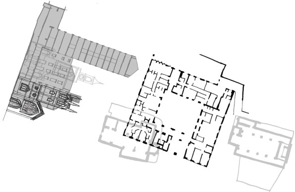
The plan is to put a 16 story tower in that courtyard adjacent to the existing tower. There are some problems with this…
Firstly the foundation design. The site is probably sat on London clay. I say probably because the CoLP won’t allow any sort of site investigation until planning has been granted since it would require a hole in the raft slab, and they don’t want one! It might have a couple of meters of gravel, but right now we don’t know. We also don’t know the ground water regime. We can guess it, and the best guess is that as soon as you cut through the raft slab water will come out. So currently the plan is to inject resin into the granular fill in order to drain the water within the working area. Gravel or not it will need piling, which leads to…
Access. The courtyard is entirely enclosed and access is via one of two vehicle “doors”. One leads into the courtyard itself and is both wide enough for a Range Rover type vehicle and tall enough for a dude on a horse. The problem with that door is that the slab that it leads onto will be removed in order to build the new building. So that doesn’t help. Behind door number two is the ramp that leads down into the basement. In order to get down to the second basement level you have to drive through the first level (that slab is coming out too) and down another ramp. You can get a low clearance piling rig, so you could drive one down. But it would be mega tricky. The better option looks like it’ll be to remove the slabs, ramps and all, and crane in the rig. There is the question of how you get the broken out slabs out. It’ll probably involve a skip, a crane and loads of pissed off people trying to get around the truck parked in the road…
There are other problems too. In order to properly assess the existing structures we went into the basement with a rebar meter. The results were a little confusing. Then we found some photos of the construction of the building and it looks like the members are steel, then encased in concrete for fire protection. Some of the transfer beams are about 2 meters deep, so breaking those out will be fun! We couldn’t get any more information as we’re not allowed to do any destructive testing until the budget has been confirmed. The budget can’t be confirmed until the planning pack has been submitted. In order to submit the planning pack we need to know what we’re doing. Which we don’t because we’re not allowed to drill a hole in the floor and find out what’s below it (among other reasons)… It’s the classic circular reference (to use an excel terminology – one for Damo).
All of this makes planning the cost of the project extremely difficult. For whatever reason WYG seem to be the only people running for this job. Maybe because it’s such a nightmare. But the in-house PM and blast analysis combination is definitely a bonus for CoLP since the new building will have to be designed to withstand an attack. That and planning this whole thing is a nightmare!
So while the structures team in Nottingham are wanting to get stuck into some Bentley action, they can’t, because if they do they might not get paid. First we have to work out what can be done, and how…
Oz NDY – IMechE CEng CPR Application Issues – Forewarned is Forearmed

This blog highlights some issues experienced of the IMechE CEng Chartered Professional Review Application process and previous academic review documentation. It also discusses hints and tips on CPR submission.
The main issue seems to stem back to the initial academic review submission that is required if your first degree is not accredited by the IMechE. I submitted my academic review back in 2012, at which time I wasn’t really clued-up on the whole chartership process. It is possible other E&M students on Ph2 might have had to do the same and could unknowingly be in a similar situation I found myself in. If so or unsure, now is the time to check and avoid it being a surprise and slight embuggerance if something needs to be submitted short notice.
The Issue
When you submit you CEng CPR application, more on that below, someone from the membership team will review it alongside your previously submitted academic review. One question on your academic review asks what level of registration you want to be assessed against. Make sure you have ticked the box for either CEng or Both. I ticked IEng only, thinking I would be awarded IEng form that point onward not realising that I would also need to submit CPR evidence and sit an interview at that stage. This was something I wasn’t planning on, thinking that I’d just wait until I had completed the MSc and simply submit CEng CPR evidence then (as I have done).
This sparked the notification that the IMechE can’t assess you for CEng if you haven’t ticked that CEng box (or Both) on the academic review. I’m still not entirely sure why, especially after explaining that nothing has changed from the initial academic review (which has IEng ticked) to the latest one I have had to submit (which has CEng ticked). Just seems like a whole lot of wasted time and effort due to a tick in the wrong box, but the process is the process and clearly some other internal shenanigans that can’t be messed with.
As for the CEng CPR application this is relatively straight forward but there are a few hints and tips I’d like to share to make it that bit smoother for when others come to do it:
- The IMechE website isn’t the most intuitive to navigate so use the link below to the application process.https://www.imeche.org/membership-registration/become-a-member/chartered-engineer/application-guidance
- Download the PDF doc and fill that in with the ability to easily edit and see what it looks like in the form.
- Download the exemplar as a guide or ask one of my cohort for a copy of theirs.
- Irrespective if you have used the PDF form or not you will still need to complete and submit the on-line form as this is linked to the application payment method. Once complete you can download a PDF of that on-line submission.
- I found it best to initially write in a word doc then copy and paste across – that way you can ensure you are within the word count, which although they say ‘approximately/around 400 words’ for each competence, they actually mean ‘no more than’ as some sections won’t let you progress if over the limit.
- The PDF form asks for signatures of your two sponsors yet the on-line form just asks you to confirm (via tick of a box) that they have read a copy of your application before you actually send it – so no need to actually get the PDF copy signed. IMechE send an email out to your sponsors anyway with a ‘no action’ verification statement.
- The on-line form initially asks you to complete your personal details prior to the competences sections. This is easiest entered prior to completing the form by going through the My Profile in Your Account. Of particular note is ensuring you enter phone numbers under the Personal and Work tabs, even though the work tab phone numbers are not *stared. I just added SI PET’s for the direct dial landline – but I’d like to think they’d call you on your personal phone first. Without these numbers entered the form seems to stop you continuing to the next section when completing on-line.
- There may be some other glitches I haven’t come across so anyone else who’s submitted forms feel free to comment.
How stuff works: post tensioning.
As I was walking around site in the beautiful sunshine of Sydney’s first day of “winter” I found myself staring at the PT cables in a new slab and wondering how it actually works. Whilst I fully understand the theory of post tensioning, I was unsure why the cables were is conduit – so my question is: if the the cables are not in contact with the concrete, how do they transfer the tension into the slab?
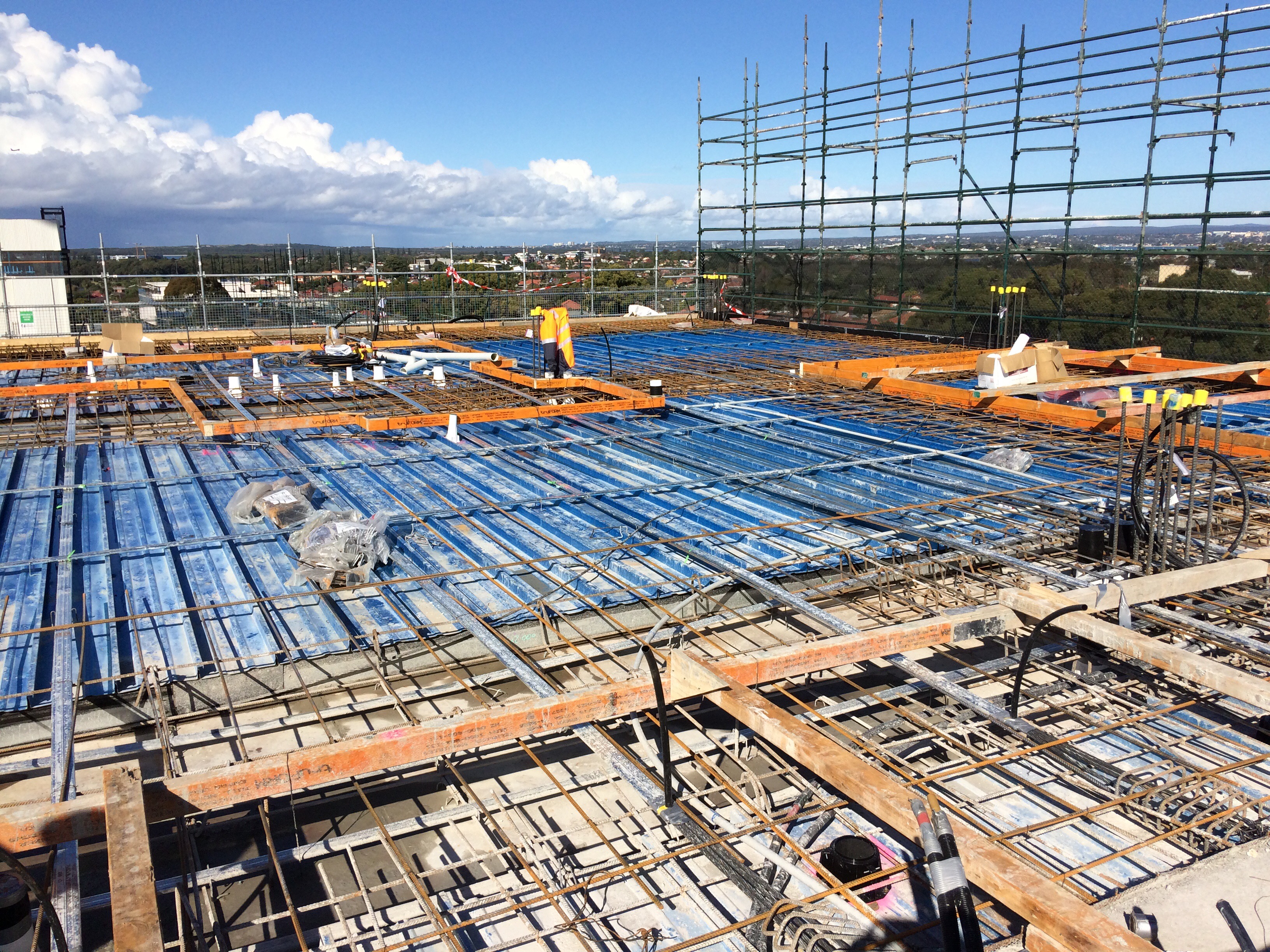
PT cables in conduits
Answers on a post card please.
Beer Economy
Has anyone else experienced the ‘beer economy’? Credit for anyone who knows the going rate for removing the three and a half blocks detailed in the picture below. It would personally take me 4 minutes with a Stihl Saw.