Archive
Temporary propping of a permanent wall
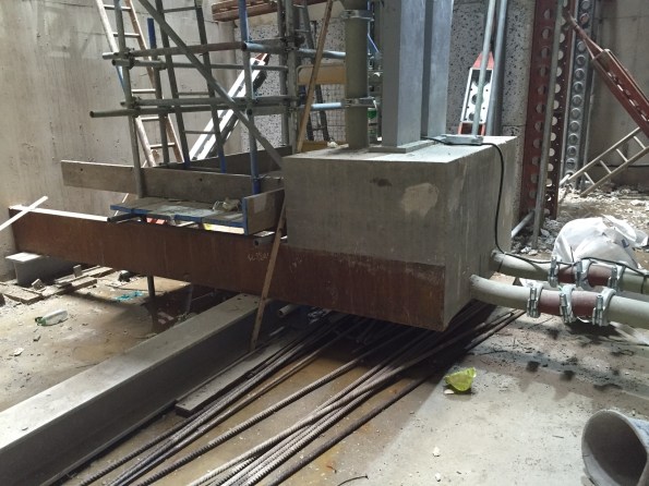
Temporary works are becoming somewhat of a theme on my site, we are moving in to the construction phase with piles and other groundworks appearing all over. I was asked to assist one of the section engineers with a design clash issue on the retaining wall I have written about previously, here is a picture to jog your memory.
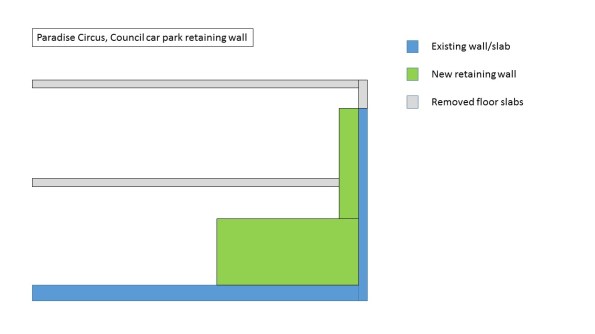 The blue wall has been temporarily propped with two levels of 45 degree square hollow sections that also prop off the existing floor slab. The design was intended to contain the lower prop and the upper prop would be removed, as shown in the Temporary propping arrangement.
Somewhere along the line, a mistake has been made either in the fabrication and installation of the props, or in the design of the wall. The lower prop now protrudes at the corner and is also required to be removed. With the base being poured in two levels (a mass concrete pour and a waterproof topper) these can be removed after the first pour.
Essentially the first base pour will replace the action of the lower prop so these can be removed. Our TW designer has asked the base concrete achieve 2/3 of the design compressive strength (approx 26.5N/mm2) before these are removed. Although in a gravity retaining wall, such as this, what affect does the strength of the concrete have?
I have a theory that the TW designer has tried to mitigate against the concrete being stripped out if it doesn’t reach the required compressive strength after the lower props have been removed. This would leave us up the creek without a paddle, as the upper props could not sustain the loading from the existing wall.
Update:
The props have now been removed and the wall hasn’t collapsed.
Pumping Iron – Not as hard as pumping Concrete
It turns out concrete can be pumped – I have been surprised how far it can be pumped if you try hard enough. The Bond Street East site contains a batching plant at Hanover Square (next to Oxford Street) feeding a pair of chunky concrete pumps. These then feed vertically down a 5-story temporary pipeline to a massive thrust block tied into a group of RC piles by big steel beams. This block enables a 90o turn before the pipe travels another 1.1km along the running tunnels to the track work sites.

Batching plant surrounded by some very expensive flats. I hope they appreciate the token acoustic sheeting.
The scale of the temporary works on these sites is fairly mind-blowing. I sit opposite the guy responsible for making this pipe work; I can assure you it is blowing his mind as well.
Concrete pipes descending from the surface to level -5
The daddy of all thrust blocks enabling a 90 deg turn.
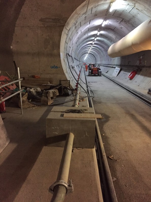
Concrete pipes disappear off into the distance to the work sites.
Unfortunately the scale of the project also creates a lot of inefficiency and interface issues. The above-mentioned pipes had to penetrate a ventilation bulkhead we had erected in a feeder tunnel. Despite being part of the same Joint Venture there was no co-ordination put in place between the teams, leading to a chest-beating discussion about who had the priority. Needless to say the concrete-pumpers won and we had to strip out our bulkhead, only to re-erect it this week. Hopefully the new-fangled BIM will put all these issues to bed. We live in hope.
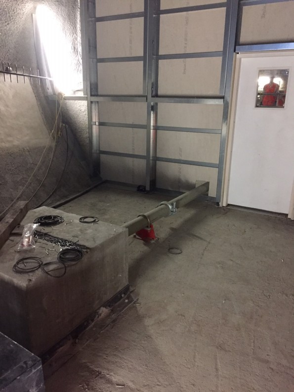
Ventilation bulkhead, version 2. Please ignore the photo-bomber in the window.
In other news I have occupied myself with a bit of ‘commercial awareness’ by firing a magazine of EWNs at Paddington station and following them through the commercial department. Not as interesting as it sounds.
We have also been lifting in some 2m x 2m x 3m silencer pods to the -2 level through the only route big enough to take them; a 5-storey vent shaft. Unsurprisingly it lost a bit of galvanisation from the corners on the way down.

Big steel box + no tag lines = swinging load. It bashed the rim of the shaft on the way in but was ok when it was inside the shaft.
Generator power
Last week one of the small projects that I have been planning since I arrived finally finished – transferring the Emergency Department (ED) onto generator power, relocating the sub-mains cables and then transferring the power back to mains.

Figure 1: Delivery of 2x 350kVA Aggreko Generators.

Figure 2: Original location of the ED sub-mains, on the floor slab of L1 (previously this had been the roof slab of the 1 storey ED). Note, the mechanical protection has already been removed.

Figure 3: New location of ED sub-mains: Now on high level cable trays in main corridor.
Rather than detail the whole process, I will instead highlight some of the risks and difficulties and how these were overcome.
- The ED runs 24/7, therefore there is no convenient time to turn off their power. But following a week long investigation of power demand, Tuesday-Thursday was identified as the period of the lowest demand and therefore the “least busy period”.
- Sizing of generators: Both 350kVA units was sufficient for the whole department, but to maintain redundancy 2 units were connects – one to Essential and one to Non-Essential (with an automatic switch between them in case of any issues).
- The hospital’s UPS (Uninterruptible power supply) was broken, therefore if power was cut all the critical infrastructure, e.g. life support machines, would switch off. This little bombshell was dropped at 1600 on the Friday before the works was due to start. The simple solution was to postpone until the UPS was fixed.
- During commissioning of the Emergency Department (2 years ago, by a different builder), the generator manual transfer switch was not tested. The risk was the hospital’s to take, therefore they were required to conduct physical switch over – the mains power was maintained at the switch until after the hospital had confirmed that it had worked.
- Fuel: although the generators had a fuel capacity to run for 28 hours at half load, in order to appease the client the tanks were re-filled every 6 to 8 hours. At no point did the levels drop below about 75%. This was a very conservative strategy but keeping the client happy is critical.
- Diesel exhausts blowing into the ED air conditioning intakes. There was only one space that the generators could go – approx 25m from the intakes – other than extending the exhaust flue by 2m (the big pipe on the ground in figure 1), this was a question of keeping my fingers crossed that there would be no complaints.
- Over night noise – the generators were rated at 70 dBA at 7m, but with EchoBarriers installed this dropped to 55 dBA. Although this made us code compliant, at 2am in a residential area it is still pretty loud. This required some more crossed fingers that there would be no complaints.
The overall project success was due to a lot of planning with the various sub-contractor and consultation with the client.
Fixed Price or Cost Plus?
I am just about to provide technical recommendations to the Client for a £350k plant movements package that I have tendered out and the potential sub-contractors have offered two pricing options for the Client to choose from. Therefore I would be interested to hear other peoples real world experience of these two options:
Fixed Price
We will sign a fixed price contract. This is a low risk option but the package is likely to be subject to continual change meaning that change requests will need to be used extensively and additional costs will be incurred due to out of scope changes, omits and additions. This means that the total cost of the package is highly likely to go over the agreed fixed sum.
Cost Plus
The potential sub-contractors have offered to sell us a set number of labour days (at gang rate) and how we use these resources is up to us. The number of days sold will be based on the current schedule and programme. This option is high risk as we could use more labour and equipment than planned and will have to pay for it but it also offers the Client with opportunity since any savings due to more efficient use of resources and due to not using the full allocation of days will go straight back to the Client. Another benefit of this commercial arrangement is flexibility. Since the package scope is likely to change numerous times, this contract removes the requirement for change requests and additional charges for change since we would simply use our allocation resources for the change. If we do use more than our allocated days of labour and/or plant, additional days will sold at a pre-agreed daily rate.
So does anyone have any experience of these two contractual arrangements and if so how did the final package costs compare to the initial agreed sum?
Conveyors, Controls and Carousels


Confusingly, no-one has taken up my offer of talking airport baggage over a coffee here from my last blog. So, I thought I might give you all an update on one of the Gatwick Baggage projects; it might entice some of you sitting on the fence to come and find out some more first hand.
The first project in the programme has now gone into construction phase, with the final design hopefully appearing something like the model below. This is an £8.1m project and, as an enabling project to the remainder of the £140m programme, must be completed by the end of the year to avoid significant knock on delays to the programme.
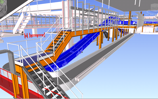
This structure is a new ‘Make up Carousel’ and consists of two new conveyors feeding a new carousel. This is the same as the baggage carousels that you will have picked you bags up from when you arrive at an airport, however in this instance, the bags have just been screened for explosive threats and will be loaded onto the aeroplane for departure.
The majority of items in this view will be new works, of which most will have to be completed in the daily window between 2300hrs and 0330hrs when the airport is non-operational.
This is the first project that Gatwick Airport, as a client, have tried their ‘package management’ approach. This involves the client taking main contractor responsibility and contracting directly with discipline sub-contractors (Structural, Civils, M&E, Controls, IT and Baggage Systems). In theory this will allow greater control and reduce project risk, though it is proving a steep learning curve for Gatwick, particularly in terms of mechanism for design collaboration between the discipline contractors. Any thoughts from other sites / design offices on approaches used by other main contractors to this would be appreciated.
Getting everything in writing. Our lead designer unnecessarily reworked an electrical design and claimed I had instructed it. When I queried, it turned out the only reference they had was a supposed telephone conversation that I don’t think took place – nothing in writing so no costs for the work incurred thankfully.
Working outside of permit. I think an honest mistake, but the M&E Contractor I am responsible for managed to complete some electrical works outside of their permit to work – on day three of being on site! Cue stopping works and incident report submissions. Not a great start for the contractor.
And finally, as the summer rush arrives and the number of stag and hen parties in the departure lounge peaks, the baggage handlers seem to be competing to see who can throw passengers’ bags the furthest when packing their baggage trollies. I think the informal record is about 4m – perhaps best not to put the bottle of chablis/ouzo in your hold baggage!
Cracking photo worth sharing…
Busy sports afternoon. Standing by for deserved abusive responses….

In my last blog I talked about the use of the top down construction methodology in the construction of high rise towers. It presents a number of considerable structural challenges which have resulted in a quite unusual and, so I’m told, unique construction sequence on our project. A senior design consultant from Sydney, Australia who is now working in the London structural engineers office confirmed that view of Friday morning when he described the 100BG basement as engineering insanity. Therefore, as it’s a Wednesday and because pictures are far more interesting than my boring text, see below some images outlining current progress.

Fig1: The concrete core, allegedly one of the largest currently under construction in Europe, is paused at a temporary hold point on floor 8.

Fig2: The full vertical load of this core is carried through steel plunge columns which are cast 5m into large load bearing concrete piles just below dredge depth. Interestingly we were able to excavate the Tower basement to 2.0m OD from 15.0m OD without use of any temporary internal propping regime.

Fig3: Sheet piles have been installed around the edge of the plunge columns to allow further excavation of the core pile cap to a depth of 0.0m OD. The Tosa pushes 6m long steel sheet piles in at a rate of approximately 24 per day. The 4m embedment seems more than sufficient to me considering they are in stiff London clay and are for the temporary condition only.

Fig4: Pile Cap excavated to depth in stiff london clay material. The water table is approximately 6m above dredge depth but ground water has not presented any issue during any stage of this excavation.

Fig5: Machinery breaking out the top of the core concrete piles in preperation for construction of the core pile cap. In the back right of the image you can see a column where the process of pouring the concrete caused the rebar cage in the column to rise in the pile shaft.

Fig6: Tower secant pile wall restraint
Pile 61 Cage Failure
A recent issue with our piling sub contractor (Skanska) has been taking up the majority of my time this week. On Friday last week whilst lifting in the top part (3 of 3) of a pile cage (Pile 61) a weld on the lifting band failed, causing three other welds to fail and the lifting band to deform. The Skanska project manager informed us that he had to stop the pile from being concreted. The lifting band is on part of the sacrificial cage that will later be removed but it there to lift and hold the cage at the right height. All good there. A good decision made on a safety and quality issue.
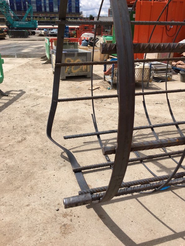
Pile 61 Sacrificial Cage Deformation
Pile 61: Diameter – 2.1m, Depth- 61m, with a plunge column.
Well, that is what we were initially told on Friday. As the investigatory wheels started turning it soon developed that not only had the lifting band deformed but that in ‘trying to make best of a bad situation’ they had taken the decision to cut off the top 2m of the sacrificial cage and tried to lift the cage from the bracing band 2m lower. This however also failed and deformed.
The decision to cut the top section and try again was not in the method statement and therefore not planned works (not authorised). The lifting and bracing bands are the same but the lifting bands have two welds where as the bracing bands only have one.
On investigation of the failed weld it is evident that there is only one weld (one side) instead of two sides, but more importantly that there seems to be no connection to the actual longitudinal bar. Very poor quality! Apparently the welder misread the drawing.

Weld seems not to have have had contact with band and not full width.
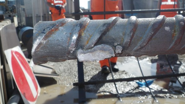
One of the failed welds, It should be 60mm (bar is 40mm diameter)
The proverbial grave got deeper as we found out that as of last week, although the cages are being produced still by the same fabricator (Express) the fabrication yard has moved from Neath (S Wales) to Newcastle. Neath went through a pretty serious quality assurance audit by both FLO and London Underground at the start of the contract. At no point was this communicated to us (the main contractor). Skanska have an engineer permanently based in Neath to quality check manufacture however do not have the same in Newcastle. Which has raised the question, how can Skanska provide quality assurance to us?
The result of all this is that we have issued an instruction to stop works until this has been resolved. This is at their (Skanska’s) cost which is evidently starting to hurt them (prelims alone are just over £10,000 a day). This morning I issued a communication (on behalf of the Project Manager) to the effect that following the site investigation diaphragm walling operations can continue however piling will be stopped until they (Skanska or Express) can provide the welding procedure, a witness statement from the welder, a CAT II check certificate for the temp wks re-bar cage remediation, revised H+S documentation and a joint inspection of the cages we have on site.
Regardless they will need to issue a Non Conformance Report as we have a 24 hour limitation for an open pile (i.e only supported with polymer fluid). But the pressure is currently on Skanska to prove the above. Funnily enough they aren’t too many smiles on their side of the office today.

RAT or Scaffold?
This time we’re on the BP Clair asset, West of Shetland, and the issue is access. Part of the scope of one of my projects is to install an additional 3/4″ drain line in the potable water storage system, in order to eliminate dead legs in which nasties such as legionella can lurk. Whoever designed the platform decided to put one of the drain valves 18m above the deck along one of the drainage pipe runs. The valve is circled in the below image (you’re looking straight up from the lowest deck level and the next deck up is the grating above and right of the valve).
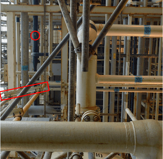
Clair Drainage Valve Location
The new drain line will run down the support structure identified by the red oblong, with a valve at deck level so that the system drains from the deck through the grating into the sea. It’s potable water so we are ok to do that.
Getting to the valve is the problem. We can’t use a mobile access platform as such things just aren’t feasible offshore. So the answer is either a rope access team ‘RAT’ who, as the name suggests, hang off the structure on ropes to carry out the work, or build a lot of scaffolding.
The RAT are expensive due to their additional qualifications and training and there are added risks in terms of them dropping stuff and delay due to adverse weather. They are however quick and there is limited impact on platform operations or other projects.
Scaffolding greatly reduces the risk of dropped objects and construction delays but requires additional manpower and is much more time-consuming, doubling the offshore execution time. It is also very heavy and gets in the way; A few weeks ago the Clair platform stopped all non-operational work until all unnecessary scaffolding was dismantled and removed.
So what’s the answer? “Well it’s a balance between time and cost, what’s the client’s driving factor for the project?” I hear you respond. That’s exactly what I have asked the platform to decide and I’ll report back on the decison. Any views from the floor on a method of choice or similar experiences?
SITE BOUNDARIES AND INTERFACES WITH ADJACENT PHASES
I have been struck by the interface between our site and the adjacent phases, in fact it was my overriding first impression on attachment. The interface issues have featured in my reports and my daily routine involves a great deal of liaison and de-confliction with adjacent sites. We have recently been constructing some temporary plinths atop a permanent structure that Phase 3 temporary bridge will sit upon and whilst conducting a pre-pour check I thought the following photo perfectly illustrates these interface issues.
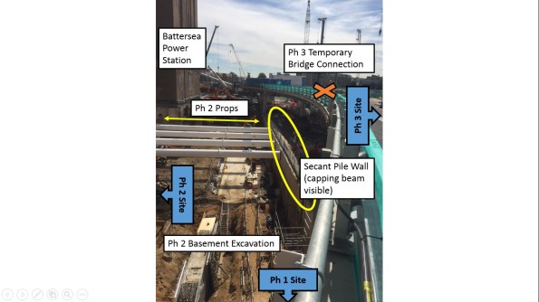
- The photo is taken looking eastward along the permanent structure (Halo Road).
- This road will provide access to Ph 1 (Carillion) for residents when the development is occupied later this year.
- Ph 3 (Bouygues UK) temporary bridge structure connects to this permanent structure (hence the plinths)
- Ph 2 (Skanska) are excavating their basement levels.
- Temporary Props have been installed in order to transfer the loads to the secant pile wall.
- Construction sequencing for Ph 3 still has to be confirmed in order to excavate basement levels on ‘our side’ of the secant wall.
- Just visible is the heating pipes that run from an M&E plant in Ph 2 across all phases to Ph 1.
As I have said previously, this is not the most technically challenging work nevertheless it is fascinating and a solid education for myself.
