Archive
Modification of post tensioned concrete
A quick reminder… I know all C’s have this covered but for the E&Ms, unlike conventionally reinforced and mass concrete, the modification of pre-stressed concrete is complicated due to the potential energy stored in the member. If suspended, all members contain gravitational potential energy but prestressed concrete stores elastic potential energy in its stressed tendons. This makes the modification, demolition and decommission of prestressed concrete members a more complex operation. Moreover, an alteration to any part of a pre-stressed member is highly likely to effect the entire structure.
With this in mind, you can imagine my horror as I was recently told I was responsible for the modification of a post tensioned slab which formed part of an exisiting structure adjacent to my project.
Sitch… In brief, I have got to co-ordinate the removal of a strip of PT slab (2m x 17m x 250mm thick), which cantilevers from ground level, over our basement, obstructing progress. Our structure will tie into the existing slab once we reach ground level. The image below shows the offender, north is up.
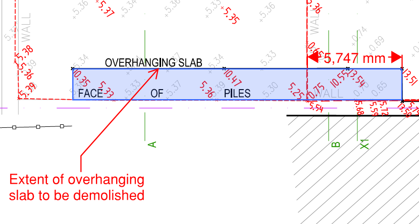
The western most 12m of the slab is 5m above our current rock level, the remainder is 10m above a lower rock level.
Thoughts so far… Having consulted almost everyone in the office, the structural engineer consultant and the PT sub-contractor I have come up with the following methodology…
Confirm effect of these works on remaining structure, temporarily back-prop remaining structure if required, back-prop the slab with falsework, provide edge protection, confirm tendon locations, expose tendons and confirm grouting, anchor the tendons with new ‘onions’ if required, cut strands, cut slab into manageable sections, sling and crane out, treat exposed edge of remaining slab with epoxy paint to prevent corrosion. Once the new structure ties in to the existing, any temporary back-propping will be removed.
I’ll take some photos and let you know how we get on.
State to check major projects after deadly asbestos found at $1.2b children’s hospital
Hot off the press:
“Two major State Government projects will be checked for asbestos contamination after deadly fibres were found in roofing panels of the new $1.2b children’s hospital.
The State Government announced the audit this morning after Health Minister John Day said tests had confirmed the asbestos.
The roof of the hospital will be replaced and could further delay its opening.
Premier Colin Barnett said the latest problem with construction of the hospital meant builder John Holland would struggle to win other Government contracts.
The contaminated panels were supplied to John Holland by a company called Yuanda.”
Yuanda (Chinese subcontractor) are supplying the façade at the New Perth Stadium, as a result we have had state government health inspectors on site all day.
Some of the newspapers are suggesting JH are sourcing ever more Chinese products since their take over last year.
All Fran’s fault….!
Non destructive testing of concrete structures
How risky is it to estimate the value of compressive strength of concrete using a rebound hammer test (RHT)?
The concrete testing failed when testing the concrete cylinders for one of our pile caps. One cyclinder failed early in shear and the other was a machine error. This means we do not have the 56 day compressive test strength for the cylinders to indicate the strength of the pile cap. We require 80MPa. At 7 days we had 60MPa, at 28 days we had 69 MPa and we don’t have a value for it at 56 days. The concrete company came out on site and conducted the RHT at 12 locations on the pile cap in question, and 12 locations on a similar pile cap as a comparison. They estimate from this test the compressive strength is 86.2MPa so comfortably above the 80MPa required. This doesn’t necessarily sit easy with me. The RHT is a test to establish the surface hardness of the concrete structure so I don’t 100% understand how this can be compared to compressive strength unless through empirical data maybe. The fact that we went from 60 at 7 days to 69 at 28 days doesn’t fill me with confidence that we will hit 80 at 56 on that current trend.
So what…..core it and test the core? or, does this pile cap actually need 80MPa therefore can we take the risk on it being borderline? – it is one of the mega piles which attaches into the core as part of the stability system though!!
I know the fact we have a bit of paper from the concrete manufacturers giving an estimate of 86.2MPa will probably suffice for BMC – someone has put their signature to it – but hardness vs strength doesn’t quite compute in my head. Have we mitigated the risk appropriately or not? Thoughts welcome.
Having sought advice….
The RHT (Schmidt) compares concrete thereby giving an indirect assessment of concrete strength. In this scenario, the test can be conducted on the pile cap in question and another similar pile cap for which we have a positive crush strength, and the results compared to estimate the strength.
BS EN 12504-2 details the procedure for doing this (thanks John). Having cast my eye over this short document there are a couple of points which are important to abide by to get reliable results:
- The surface must be smooth to get an accurate result so any rough surfaces must be ground down first.
- Test locations between comparative structures must be tested under similar conditions and they should be tested at similar positions to reduce any possible effects due to differences in rigidity and uniformity of concrete.
- Moisture condition of the surface should be consistent throughout the testing. Dry surfaces are preferred.
- The coefficient of variation of individual readings within one test should be in the order of 10%. It should decrease with an increase in strength.
You now know what you can do, just in case any of you end up in a similar position!!
Spot the mistake No 2
I am beginning to dread Monday mornings!We are just about to backfill the core and are in the middle of a commercial minefield. We have 50% of the footings complete and 30 % of the slab on ground, with the southern half of the site still bare rock and some more excavation to get down to bulk.
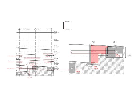
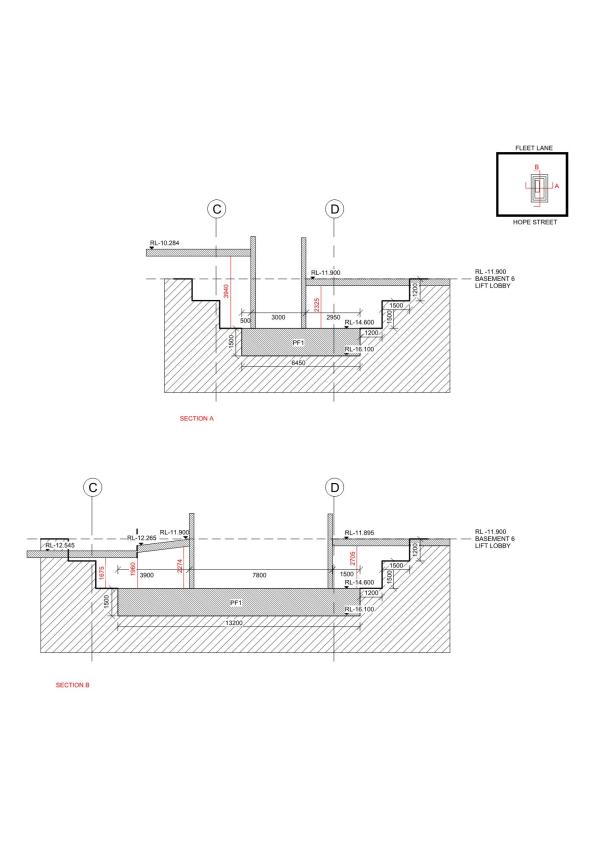
I am dealing with the restraint of the secant pile retaining wall on my site and I was asked to look at a build sequence to remove the anchor waler, that is going through the strip retaining wall. The very helpful wall designers then told me that I had to build the slab above then remove waler. Now this is designed as a slab on ground and the area in red needs to be backfilled. So I challenged that I only had to backfill to the bottom of the waler with compacted fill- They conceded.
Hurrah – smug for no reason, I go about my business until one of my cadets asks me how the wall is tied into the central core as there are no details of the connections. Now I am not in charge of this wall as it belongs to the ‘lone ranger’ but, he wasn’t interested in what cadet had to say (the cadet is exceptionally bright). I also know this wall is 18 m long and nearly 3 m deep and cannot be supported by the lift core and the secant pile wall. So how is it supported?
Smelling a rat -I check with the Project Engineer who tells me it doesn’t need to tie into the core as it is supported by the slab on top and bottom. What did they miss and how should I solve the problem? I look forward to hearing your suggestions.
Plan view here S-CD-10-001_3-Markup Retention wall

The Crossrail Oil Tanker
In keeping with my esteemed colleagues I am joining the post-AER blog party.
The scale of the Crossrail project coupled with the number of stakeholders involved leads to an awful lot of inertia within the organisation. To push a bad nautical analogy the Crossrail oil tanker makes the British Army bureaucracy feel like driving a particularly nippy frigate.
As part of the tunnel ventilation contract ATCjv has to justify the access and maintenance strategy for the end user (Rail for London, the Crossrail arm of TfL). This includes ensuring the designs allow for the replacement of equipment during the 100-year design life of the stations. I have been attempting to re-write the access and maintenance strategy for a system of dampers installed in a 3 x 3 grid against wall openings at the Paddington Station platform level.
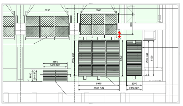
A drawing showing the damper installation – the space available for an access and maintenance crane is shown by the red arrow.
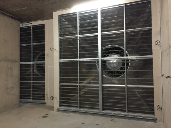
Some similar damper banks installed at Bond Street station
The means of replacement of these damper units was a scope gap in the initial works information for the station contractors. As the stations are running well behind schedule this scope has been moved over to ATCjv on a ‘Cost +’ contract. This is clearly a lucrative deal for ATCjv that has not incentivised the company to seek a low-cost solution in any way. The resulting design is for a series of gantry cranes to allow the replacement of the dampers.

Kone gantry crane in Canary Wharf station – similar to that proposed for the damper access and maintenance strategy.
In the case of Paddington station this solution is not suitable for the following reasons:
- There is no space for the gantry crane on the downstand beam (see drawing detail at top and below).
- The gantry crane would not be able to access the top of the damper frame to remove it (making the whole installation pointless).
- It’s a massively expensive solution to a simple problem.

Gantry crane proposed design. Damper units are the pink louvers in the 3 x 3 grid, crane outline is shown in red. Note the position of the crane hook is below the top flange of the uppermost damper unit leaving no allowance for slinging the load.
Rather than mess around installing and then maintaining a series of electric cranes I am trying to justify using a portable material lift instead:
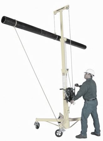
Mechanical material lift, kindly modelled by Mr Tom Docker
Here lies the oil-tanker. Getting this solution approved has required meeting with the end user, maintenance staff, station main contractors, crane installers and Crossrail representatives. The justification has included a feasibility study, cost-benefit analysis and a new access and maintenance strategy. This process has been ongoing for two months, and will hopefully be concluded before I depart for phase 3.
The scale of commercial manoeuvring and arse-covering has been pretty impressive and has given me some pretty good insights into the importance of writing a tight contract instruction. In this way Crossrail could have maintained focus on a simple and common-sense solution to prevent the problem running away into a taxpayer money-pit.
I am guessing that everyone will have a similar example from their own sites; has anyone been successful in actually putting an issue like this to bed?
Mark
Spot the mistake
The sub-contractor wants to backfill the core (big hole in the picture) with spoil from on site to support the slab on ground that will be locked into the lift core. The core is currently open with 1.5 m benches down the base footing and the backfill will be approximately 3 m deep.
The material is crushed phyllite which has ended up like brown clayey GRAVEL. I needed a CBR of 15 the CBR rating indicates 20, what did I miss. CBR link.
I was talking to the Geotechnical Engineer when I discovered that I am idiot (we already know that my subbie is an idiot). Hint the core is likely to be wet.
Propping against air
I have been presented with this issue today. The groundwork contractor, Churngold, have been given a package to construct a large retaining wall that will replace a wall which was being propped by a podium deck and intermediate floor slab. See the below drawing.
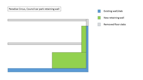
The wall is being cast in three stages. 1) Mass concrete footing. 2) Waterproof concrete on footing and kicker. 3) Waterproof concrete for wall. Stage 1 is due for completion on Monday 8 Jul.
The formwork is a proprietary system from Mabey and requires soldiers at 1.5m centres at 1.66m height and with a leg of 1.6m. See the below photo to identify formwork.
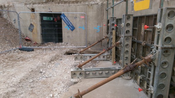
As can be seen in the above photo there is a section of slab that has been removed as part of the demolition works, from which the groundworks contractor were planning on propping against.
My options for the solution to this so far have been.
a) Cast footings where required.
b) Redesign propping system.
c) Cut short pour with a stop end to a safe location where the propping is stable against the slab.
d) Mass pour a slab in the hole and allow the subcontractor to prop against this on Monday.
My initial thoughts are a combination of a) and d) which will appease both the QS and the subby. However I need to satisfy myself that the prop loadings will be taken by the slab under 3 day strength (assuming the concrete is poured on Friday 5 Jul), and secondly that the backfill material will take the load from the slab and prop loadings.
Project or Programme?
You will all have been waiting eagerly to hear how the execution of my caisson swage repair went. I mentioned in my earlier post the issues with a crane outage and competition for deck space in the laydown area. It also transpires that the HVAC in the Bruce utilities room (see image) where the work will take place is not working, thus making the room a confined space. These issues have conspired to push the scheduling of the C16 back into late September.

Bruce Utilities Room
By pushing the timing of the C16 repair back, it aligned with the scheduled repair of the next caisson, C15. With typical military enthusiasm I claimed this second repair as my own project and it became clear there were efficiencies to be made by completing both repairs back to back. Wood Group, BP’s engineering partner have produced a combined construction schedule and the saving of combining the work scopes is in the order of £200k.
At this point I hit yet more issues as the repair is dependent on an inspection being carried out by the Integrity Engineering team. This inspection can’t take place until the core Bruce engineers remove the pump and its riser, the sectional pipe that connects the pump to the distribution pipework (top right in the above photo). It transpires that the riser from C16 is sat in the racking in the utilities room (bottom left of the photo). Guess where the C15 riser needs to be put?
So what we have ended up with is a series of 3 related projects all with elements of their scope which are similar, taking place as a sequence, in the same place. From what was covered on the APMP course that sounds very much like a programme. Treating the 3 projects as a programme and appointing a programme lead should ensure any issues which affect the other projects are identified and mitigate and may lead to further efficiency savings.
As if my first project growing arms and legs and becoming a programme wasn’t enough I have been tasked to conduct a portfolio risk review for all the projects being undertaken by the Projects and Modifications team.

