Archive
Testing & commissioning
After a long delay the Crossrail tunnel vent team have finally completed a project in my patch, all be it only a temporary installation. The temporary tunnel ventilation (TTV) was supposed to complete by the end of Jun, but was finally finished on the 18th Aug; six weeks late on a three month programme. This blog describes the issues that caused the delays and the process of testing and commissioning.
The Bond Street temporary tunnel ventilation will be in continuous operation for over 18 months and is designed to apply fresh air to the running tunnels for construction ventilation at a design rate of 200m3/sec. The four fans are now installed at the -5 level within the Bond Street station construction site. They supply fresh air to ventilate the construction works within the running tunnels.
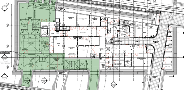
Plan view of the Bond Street Station TTV installation at the -5 level.
Despite some site access issues the mechanical install was completed to schedule. However, the station main contractor (Costain-Skanska JV) was responsible for the temporary power supply to the installation. They encountered the following delays, mostly due to poor planning and co-ordination:
- The main incomer to the site (from the District Network Operator) was installed with a different phase rotation to the rest of the site. The DNO is a law unto itself and would only come back to site to fix the problem on their terms; this relatively simple process caused CSjv a two week delay.
- The main supply cables to the fans were sized on a ‘back of fag packet’ estimate by an untrained installation contractor. The calculations were not checked by the main contractor electrical installation management. The cables ended up being undersized by about 20%; this required another 250mm2 cable to be run through the running tunnels to supply the feeder pillar, resulting in another 2 week delay.
- The temporary supply cables feeding the vent equipment were supported on the site hoarding; the weight of the cables caused the whole edifice to bow inwards towards the site. Once discovered by the site temp works co-ordinator this installation was condemned and a bespoke cable route had to be constructed. Another 4 week delay.
- The site electrical distribution protection was set to 25% of the circuit breaker (CB) rated power of 1600A. Each of the four fan motors draws 350A at full power. As a result the total power drawn was 4 x 350A = 1500A, way more than the CB setting of 400A. As the fans were run up beyond ¼ power during commissioning the CB cut the supply under load (making a sound like a bomb going off). It took another four days to find a specialist who could adjust the incomer CB to the correct setting.

The DNO searching for the phase rotation problem behind the site main transformer.
When the system was finally energised on the 16th Aug we instructed the vent installation contractor (Hargreaves Ductwork Ltd) to commission the system. Surprisingly, this was not a particularly high-tech process and followed a logical order of testing the safety systems first, then functioning of the fan motors before testing the air flow rates. The stages undertaken are outlined below:
- Emergency stop test. The fans were run up to 25% in pairs before hitting the remote emergency stops at the guardroom. No issues here.
- Fan Vibration Tests. The fan motors were started and tested for vibration using a handheld accelerometer. This measures the peak acceleration in all three axes. The peak values were recorded to compare against the readings at the first service interval in six months’ time.
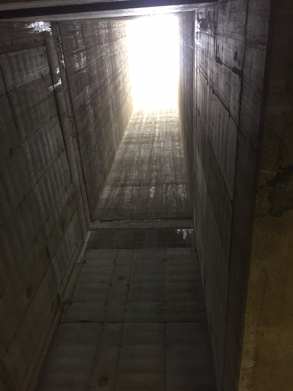
Airflow path going down through the station structure.
- Fan Air Path. The fan motors were run up through 25% increments to 100% to see if the flow created had any adverse effect on temporary works and debris in the site. At full power the air drawn in through the station was moving at 20 m/s – very windy. This flow was enough to pick up lumps insulation material from two levels above and send it through the fan blades!
- Tunnel Air Flow Rates. The airflow rates were measured from a simple average flow using a anemometer in a grid pattern in the tunnel cross-section, as illustrated in the image below.
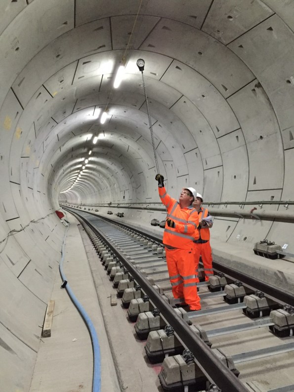
Big Ralph using the flow rate measurement grid.
Completing the T&C process marks the end of the temporary tunnel ventilation construction. The installation has been a useful dry-run for ATCjv and our sub-contractors as it has highlighted a number of issues posed by working in an underground site and within the rigid Crossrail quality control procedures. These issues can now be anticipated for the larger scale permanent ventilation installation that is currently ongoing.
On another note is hasn’t been all work and no play. Gary Jackson and I entered a navigation competition in an RAF aircraft and won it! The prize was presented by the Duke of Edinburgh, see below. Most importantly the event included a free bar…

Big Phil presenting a big prize.
Plinths for MSBs
Not the most exciting blog from me, but any assistance would be appreciated. Has anyone dealt with plinths for mechanical switch boards (MSB)? They are all being installed in ground level plant rooms of a sports stadium – some of which house AHUs and significant ‘wet’ pipework. Having dug into the specifications, there appears to be no requirement…?
That said, I presume it would good engineering practice to install a concrete plinth to aid installation, routine maintenance and prevent damage.
Anyone know about Friction?
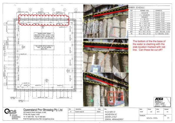
I have another problem, the bottom brackets of my walers clashes with my basement level 5 slab-exactly what we wanted to avoid. So I need to cut the brackets off before I can lay the slab. My sub contractor who designed the waler is not so happy with this idea.
My email below:
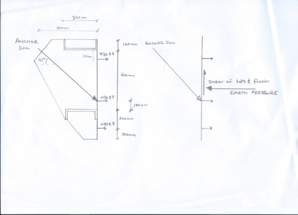
There are currently 12 bolts either side of the anchor. If we removed the four bottom bolts this would leave 8 bolts remaining.
These bolts are AS1252 M30 8.8/s with a shear capacity of 214 KN. Which would leave the bolts with a total shear capacity of 1712 KN not including the friction of steel on concrete. If I look at the anchor summary Q2454-0007 and apply the vertical shear at 45 degrees from the safe working load I get the following:
| Zone | Anchor SWL (KN) | Calculated vertical shear (KN) 45 degrees | Factor of safety |
| 3E | 1244 | 880 | 1.95 |
| 4A | 1316 | 930 | 1.84 |
| 4B | 1280 | 905 | 1.89 |
| 3D | 1160 | 820 | 2.09 |
Even if we factored the SWL by 1.5 this would still be within the capacity of the 8 bolts. Please slap me down if I am being an upstart…
I have since read a paper that indicated the coefficient of steel on dry shotcrete as 0.57, which could potentially reduce my shearing force by 467 KN. Now part of the problem I believe is that the ground anchor does not act through the ‘middle third’ of the waler and so there is a moment induced and the bolts therefore act in tension and shear reducing their capacity. How do I get around this and still cut off the brackets?
I have had a look at the UK’s Steel Bluebook and I think that with the bolts in tension the shear capacity is reduced to 80% – I am having issues looking at Australian Standards at the moment though to confirm what they use here. Any help gratefully received.
The offensive article:![Q2454-0102[A]](https://pewpetblog.com/wp-content/uploads/2016/08/q2454-0102a1.jpg?w=595)
For you Richard:
Arching effect in soils
 Secant wall bending in towards the soil
Those of you that have read my blogs will realise I am having a few issues on site. I have now stopped excavating and have started to build back up. In order to build our stairs we needed to remove an anchor waler. We asked permission from the designers 6 weeks ago, but were ignored. We asked several times more and the designers refused to take our calls. So needing to make progress we sent an ultimatum on Aconex, email and in writing, we would remove the waler on a given date and if they didn’t get back to us then they agreed that it is safe to proceed (for my own sanity I did a free earth model and compared against the wallap analysis for the new case). That date passed and we removed the waler on Friday 19th. The stairs will be built in the next 2 days and will restrain the piles from then.

Ground waler removed from wall so stair can be built.
When I inspected the wall after the waler had been removed I expected movement towards the hole. What I found was the wall had actually moved outwards. The wall is buried in low to medium strength phyllite and this is clearly stiffer than the piles so the ground has arched to the remaining ground anchor walers.
I have regularly inspected the wall and there are no signs of cracking or further deformation. The load has moved elsewhere! If you look at the first photo you will see a slight bow inwards of the shotcrete.
Here comes the science:
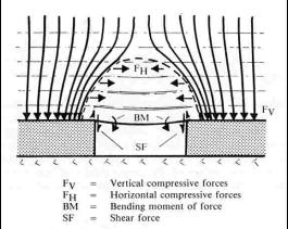
“Arching occurs when there is a difference of the stiffness between the installed structure and the surrounding soil. If the structure is stiffer than the soil then load arches onto the structure. Otherwise, if the structure is less stiff than the soil then load arches away from the structure.
For instance, if part of a rigid support of soil mass yields, the adjoining particles move withrespect to the remainder of the soil mass. This movement is resisted by shearing stresses which reduce the pressure on the yielding portion of the support while increasing the pressure on the adjacent rigid zones. This phenomenon is called the arching effect.”
Piling by estimation
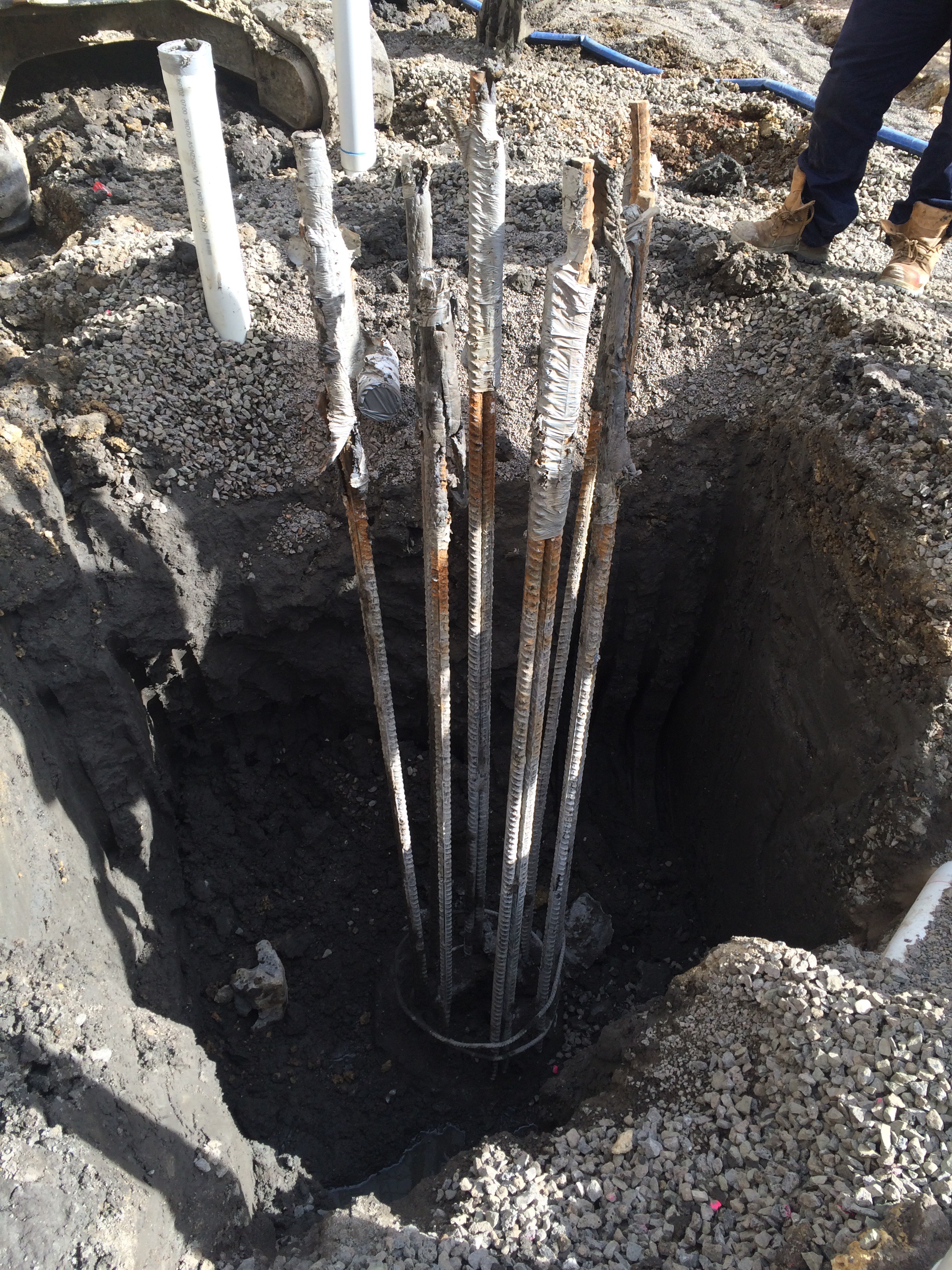
This slide show lays out the basic process to piling at Paradise.
Piling began in Paradise three weeks ago. The piles are 1200mm bored RC piles working in end bearing. Each pile requires a rock socket length of approximately 6D.
Despite the management issues with the demolition subcontractor being currently 9 weeks behind schedule and still on site, the piling has been going well. The target has been to complete 2.5 piles per day and the pilers are currently hitting around 3 per day.
The estimation that the piling is working on is that of the rock head level (m AOD of the incredibly weak and completely underwhelmingly named “Bromsgrove Sandstone”). The rock head level is required 10 days before the piles are installed and this has been assumed based on previous construction drawings that show the underside of foundation levels. This level effects the overall length of the pile and more importantly the length of the steel reinforcement cages, hence the lead time.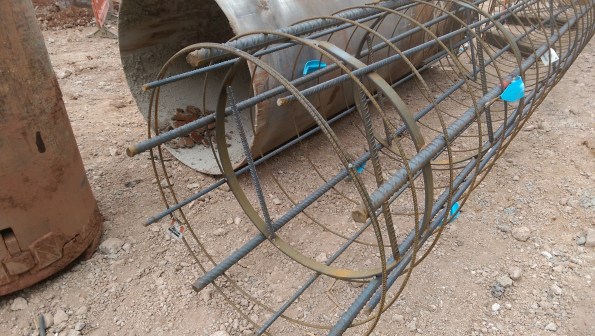
The issue I had yesterday on site was an obstruction encountered below the presumed rock head level. This obstruction appeared to be a concrete slab, possibly blinding, at about 5.5m below piling mat, the rock head should be 4.25m below. A quick inspection of the piling hole identified the sandstone was collapsing above the obstruction and water was trickling in to the base.
The piling designer was contacted and assured everyone that the rock socket length could still be achieved by increasing the depth of the pile, but not the length of the cage, so the bottom 1.25m would have no structural steel. (Revision – due to additional length in the cages the actual length without steel is only 600mm). This pile will be recorded as a non-conformity by the piling sub-contractor and I will advise that further testing be carried out on this pile.
This pile is located in the core of the structure and as such I am now concerned that the surrounding piles will also have a rock head level lower than expected. When we do the surrounding piles (Approx 3 days after that pile in question – Monday) I will be able to get a better idea of what the obstruction is.
SITE FATALITY: INVESTIGATION PROCESS
Moving on to the investigation side of things. As in the UK, the situation is slightly complicated by the fact that the incident took place on military/federal/government property. There will be no less than 4 separate investigations, and potentially 2 separate court cases. I will do my best to explain them, and what has happened so far:
CID (Criminal Investigation Division): The equivalent of our SIB, this is a military body that immediately took control of the site, closing it down and undertaking the initial ‘crime scene’ investigation, including taking photographs and evidence etc. The investigation is military and aimed at documenting the incident, as well as trying to determine if there is any criminal negligence. This report is not necessarily made available to the public, but can feed a potential criminal investigation.
OSHA (Occupational Safety & health Administration): The closest thing to our HSE. Under Federal law OSHA were contacted within 8 hours and took over the site once it was handed over to them by CID. OSHA represent the Federal Department of Labor [sic], this investigation is open to the public and transparent. This investigation will focus on what caused the accident, and who was at fault. It focuses on any violations that may have taken place, and particularly on any ‘willful violations’. It can apportion fines to those responsible, all of which are paid to the Department of Labor.
Contractor Investigation: The sub-contractor have five days to produce their own incident report, which is then passed on to USACE and feeds the USACE investigation.
USACE: An internal investigation aimed at understanding what went wrong, as well as making recommendations and generating ‘lessons learned’. The investigation establishes an ‘Executive Incident Board’ comprising 6 personnel from across the Corps (military and civilian), who are experts in their fields and are given considerable powers to investigate the incident from a military (non-criminal) perspective.
Once these investigation have been concluded, which could be as soon as six months, but likely to be much longer, there are then court proceedings to consider:
Civil Court Case: Likely to be sought by the family of the deceased in order to claim compensation from those deemed to be responsible. Any awards here would be made to the relatives of the deceased, as opposed to fines paid to the Department of Labor under the OSHA investigation.
Criminal Court Case: Potentially sought by some branch of the government against anyone likely to be criminally liable. As in the UK a higher burden of proof is required to obtain a conviction in a criminal case over a civil one. Depending on the investigation(s) the truck driver could potentially face a charge of ‘vehicular homicide’, which in Maryland can carry a custodial sentence of ten years.
Both civil and criminal trials have the ability to subpoena information from any of the plethora of investigations conducted.
SITE FATALITY: INCIDENT UPDATE
So following on from my SITE FATALITY blog on Friday. After speaking to the project Safety Manager and others the situation has become a little clearer. Without wanting to overrun the blog, I’m going to write a piece confirming the circumstances of the accident, and a second outlining the investigation process so far, and moving forwards.
Firstly, the incident: As expected, the information I received on Friday was generally correct, but wrong in a few key areas. Here is an update:
A third-party (AI) delivery of aggregate was received on site. This delivery was ordered by the concrete sub-contractor (DCB), who were therefore responsible for the delivery for the whole duration of his time on site. The truck drove around to the specified delivery site, then reversed off the road and down an incline in order to discharge the aggregate. The surface of the incline was dusty, so once the mass of the aggregate had been removed from the flatbed, the truck lost traction with the surface, which is why it got stuck and needed to be recovered. So potentially some culpability for the General Contractor (MG) who failed to provide safe site access (no matting or aggregate etc. etc.). There was no tow-bar on the front of the truck (potential culpability for AI), so a tow-strap was attached to the front axle and the vehicle recovered to the track. At which point the truck driver exited the vehicle (left-hand side), and walked around to the rear of the truck in order to secure the tailgate. Whilst this was happening two sub-contractors (DCB) moved forwards (from the right of the vehicle) to undo the tow-strap. One wedged himself under the front right tire to give himself enough leverage to work the straps, whilst the second handed him tools. There was no spotter or banksman (so potential culpability on behalf of both DCB and MG for not following site best-practice). The truck driver, unaware of this activity climbed back into the cab and without doing a vehicle walk-around or checking that he was clear drove off crushing the first man, and knocking the second over (potential culpability for both the delivery driver (AI) and also MG for not properly briefing, training or supervising him). It appears that all of this happened so quickly that the MG foreman was not aware of it until after the incident. There could quite easily have been two fatalities that day.
The investigations have started, but it is likely to take some time for conclusions to be reached. It is the opinion of the Project Safety Manager (and myself) that all three parties will be found liable to some extent; it is just a question of the proportionality of blame. Ultimately, according to the contract and site-practice over here, the delivery was the full responsibility of the sub-contractor DCB (not the General Contractor (MG)), who may be found more liable than the others. Though this is just conjecture on my part at this stage.
SITE FATALITY
Unfortunately a concrete sub-contractor was killed on the East Campus site earlier today.
I wasn’t on site at the time, and the accident didn’t occur on the JOC project. However there are four construction projects taking place concurrently across the East Campus site, all of which utilise the same access routes and co-ordinate closely. The incident took place only a few meters from the JOC building, and JOC personnel where amongst the first on the scene, and to attempt first aid. All USACE personnel are based in the same site-office, and a number of them (including Safety Managers) are double-hatted across two or more projects. The accident appears to have been entirely preventable.
In my first blog I made the following off-handed remark with regards to site traffic: “someone had a cunning plan which involves not enforcing any sort of traffic management plan and only vaguely checking who moves to and from site, which has alleviated some of the congestion”. Perhaps traffic management was a contributing factor, and maybe I should have pushed this further at the time rather than brushing it aside. The fact is someone who turned up to work today isn’t going home. Here are the salient facts as I understand them at the moment:
A dumper truck arrived on site and was directed to the appropriate area. When he arrived at the designated spot he pulled off the site access road in a forwards direction in order to discharge his aggregate. At which point he became stuck. A recovery vehicle was called for, which, after attaching a sling to the rear axle of the dumper truck pulled the truck back onto the access road. The sub-contractor in question moved forwards and crawled under the truck in order to detach the haul-sling from the rear-axle. The driver of the dumper truck, unaware of this, put the vehicle in reverse and accelerated off in order to maneuver his vehicle around so that he was facing the right direction to exit the site. Workers quickly stopped the driver, but by this time it was too late. The sub-contractor was crushed under the wheels of the truck, and despite attempts could not be revived. I haven’t been able to ascertain what if any hand signals or communications there were between the truck driver and any banksmen/site workers, or if there had been any specific (beyond the obvious) breaches of site safety protocol.
Obviously work was stopped across the site for the day and an investigation has been opened, which may provide some answers.
It seems slightly macabre to turn this into a discussion topic so soon after the event, shocking as it is. I’m sure lots will come out of the investigation, but from what I understand so far it looks like a combination of poor communication, corner-cutting and an uncertain/ever-evolving traffic management plan. This accident should not have happened!
I’ll update as the situation develops, but if anyone has any initial thoughts please let me know.
Self build crane
![IMG_4244[1]](https://pewpetblog.com/wp-content/uploads/2016/08/img_42441.jpg?w=595)
A few weeks ago someone asked how cranes can self build. My neighbouring job is, as I type, building the next level of the crane. The sections of tower are placed on the platform to the left of the tower and the tower is the jacked up so the next section can slide in. You can see one piece about to be slid in and the next on the hook.
![IMG_4245[1]](https://pewpetblog.com/wp-content/uploads/2016/08/img_42451.jpg?w=595)
The first piece has been slid in and the crane is jacking itself up to take the second piece.
I need to have a word with myself because I thought this was cool.
