Testing & commissioning
After a long delay the Crossrail tunnel vent team have finally completed a project in my patch, all be it only a temporary installation. The temporary tunnel ventilation (TTV) was supposed to complete by the end of Jun, but was finally finished on the 18th Aug; six weeks late on a three month programme. This blog describes the issues that caused the delays and the process of testing and commissioning.
The Bond Street temporary tunnel ventilation will be in continuous operation for over 18 months and is designed to apply fresh air to the running tunnels for construction ventilation at a design rate of 200m3/sec. The four fans are now installed at the -5 level within the Bond Street station construction site. They supply fresh air to ventilate the construction works within the running tunnels.
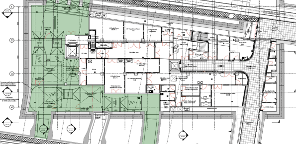
Plan view of the Bond Street Station TTV installation at the -5 level.
Despite some site access issues the mechanical install was completed to schedule. However, the station main contractor (Costain-Skanska JV) was responsible for the temporary power supply to the installation. They encountered the following delays, mostly due to poor planning and co-ordination:
- The main incomer to the site (from the District Network Operator) was installed with a different phase rotation to the rest of the site. The DNO is a law unto itself and would only come back to site to fix the problem on their terms; this relatively simple process caused CSjv a two week delay.
- The main supply cables to the fans were sized on a ‘back of fag packet’ estimate by an untrained installation contractor. The calculations were not checked by the main contractor electrical installation management. The cables ended up being undersized by about 20%; this required another 250mm2 cable to be run through the running tunnels to supply the feeder pillar, resulting in another 2 week delay.
- The temporary supply cables feeding the vent equipment were supported on the site hoarding; the weight of the cables caused the whole edifice to bow inwards towards the site. Once discovered by the site temp works co-ordinator this installation was condemned and a bespoke cable route had to be constructed. Another 4 week delay.
- The site electrical distribution protection was set to 25% of the circuit breaker (CB) rated power of 1600A. Each of the four fan motors draws 350A at full power. As a result the total power drawn was 4 x 350A = 1500A, way more than the CB setting of 400A. As the fans were run up beyond ¼ power during commissioning the CB cut the supply under load (making a sound like a bomb going off). It took another four days to find a specialist who could adjust the incomer CB to the correct setting.

The DNO searching for the phase rotation problem behind the site main transformer.
When the system was finally energised on the 16th Aug we instructed the vent installation contractor (Hargreaves Ductwork Ltd) to commission the system. Surprisingly, this was not a particularly high-tech process and followed a logical order of testing the safety systems first, then functioning of the fan motors before testing the air flow rates. The stages undertaken are outlined below:
- Emergency stop test. The fans were run up to 25% in pairs before hitting the remote emergency stops at the guardroom. No issues here.
- Fan Vibration Tests. The fan motors were started and tested for vibration using a handheld accelerometer. This measures the peak acceleration in all three axes. The peak values were recorded to compare against the readings at the first service interval in six months’ time.
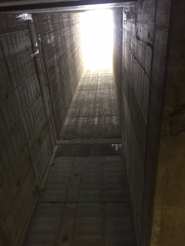
Airflow path going down through the station structure.
- Fan Air Path. The fan motors were run up through 25% increments to 100% to see if the flow created had any adverse effect on temporary works and debris in the site. At full power the air drawn in through the station was moving at 20 m/s – very windy. This flow was enough to pick up lumps insulation material from two levels above and send it through the fan blades!
- Tunnel Air Flow Rates. The airflow rates were measured from a simple average flow using a anemometer in a grid pattern in the tunnel cross-section, as illustrated in the image below.
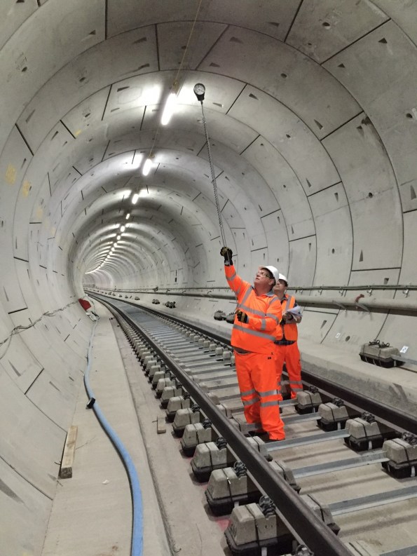
Big Ralph using the flow rate measurement grid.
Completing the T&C process marks the end of the temporary tunnel ventilation construction. The installation has been a useful dry-run for ATCjv and our sub-contractors as it has highlighted a number of issues posed by working in an underground site and within the rigid Crossrail quality control procedures. These issues can now be anticipated for the larger scale permanent ventilation installation that is currently ongoing.
On another note is hasn’t been all work and no play. Gary Jackson and I entered a navigation competition in an RAF aircraft and won it! The prize was presented by the Duke of Edinburgh, see below. Most importantly the event included a free bar…
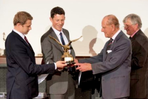
Big Phil presenting a big prize.

Hi Mark,
All sounds like good experience.
I don’t understand how the DNO supply phase rotation on your incomer can be different to the rest of site. Is it not just as simple as doing a cold phase rotation check prior to making terminations? Or is there more to it than that in this situation?
I’ve recently had the pleasure of getting a “specialist” out to input the protection settings on some VIP relays for HV circuit breakers and found that Google and I knew more than he did, which was worrying.
Get anywhere with BWL?