Archive
‘ealth and Safety gone mad
I am trying to complete the mountain of paperwork required to get permission for a sub-contractor to start on site. One of the checks is to ensure that the workers have valid medical certificates to operate safety-critical plant equipment. Anyway these medicals are valid for 3 years but some Health and Safety ‘ninjas’ on my project have stipulated that all medicals must have been completed within three months of starting on site. the subbies I am working with all have certificates that will be 3.5 months old upon starting.
So quite rightly the sub-contractor has challenged this requirement since if this was the case on all sites, then companies would have to have their workers examined up to fours times a year – 8 times more often than an airline pilot! This would also incur additional, unnecessary cost that will inevitably be passed onto the Client.
So I challenged this rule and asked whether it is based on any form of science i.e has research shown that those with a recent certificate have less sick days. The answer was no – the decision was made during a meeting and the figure of 3-months was plucked out of thin air and agreed upon.
You may be able to tell that I am finding this kind of ‘golden plating’ frustrating and so try to challenge it wherever possible.

Anyway, after challenging this with the health and safety team, I have secured approval for the subbies to start on site.
Has anyone else come across similar examples of the H&S Team unnecessarily gold plating the H&S regulations without any fact or logical reasoning behind it?
“Erm, the Grab is stuck!”
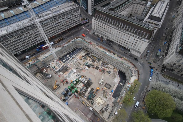
I was in the process on drafting a general update on the progress on site but late on Friday the piling sub-contractor’s world started caving in and it dragged me in. On Friday at 1900 (perfect timing like all great catastrophes) I, with the Project managers for FLO and Cementation Skanska were scratching our helmets, one of the diaphragm wall grabs was stuck at 60m. The situation worked itself out in the end but at the time, all options seemed bleak.
The background
The grab first got stuck at a depth of 60.5m depth around 1300. This meant it had 0.5m left to dig before the sub contractor long weekend. Either before or in the process of trying to release the grab, the rig had a hydraulic failure and lost 50 litres of hydraulic fluid. At this point it was hoped that the hydraulic failure was the reason it was stuck.
Unfortunately after the endless calls to Germany, diagnostic and repair the grab was still stuck. Shock loading and constant load of 42 tonnes for 3 hours didn’t work. The rig is about 160 tonnes on crawler tracks. The grab itself weighs 20 tonnes and is about 10m long. The lifting cables are rated to 100 tonnes.
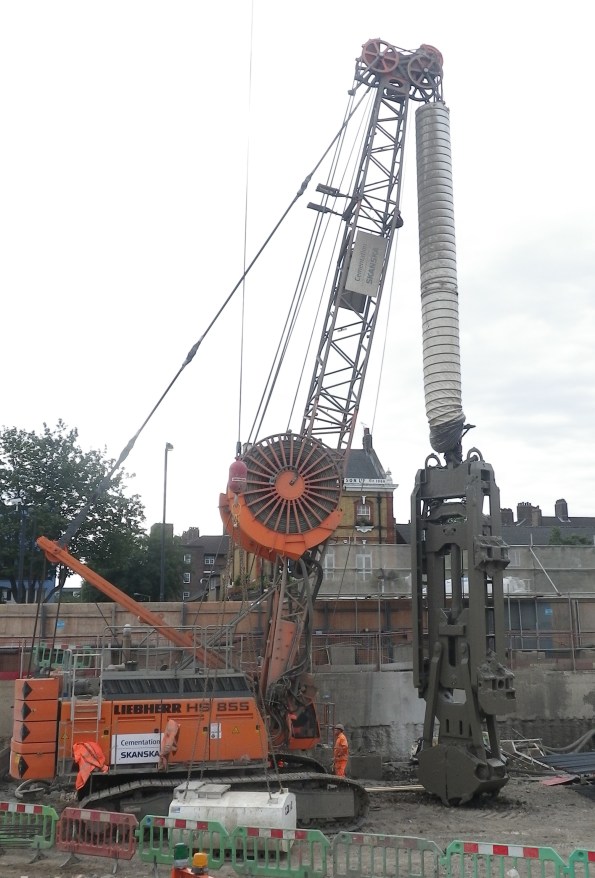
The diaphragm wall rig and grab unstuck
Options
As we stood around the rig in the quiet site we discussed three options.
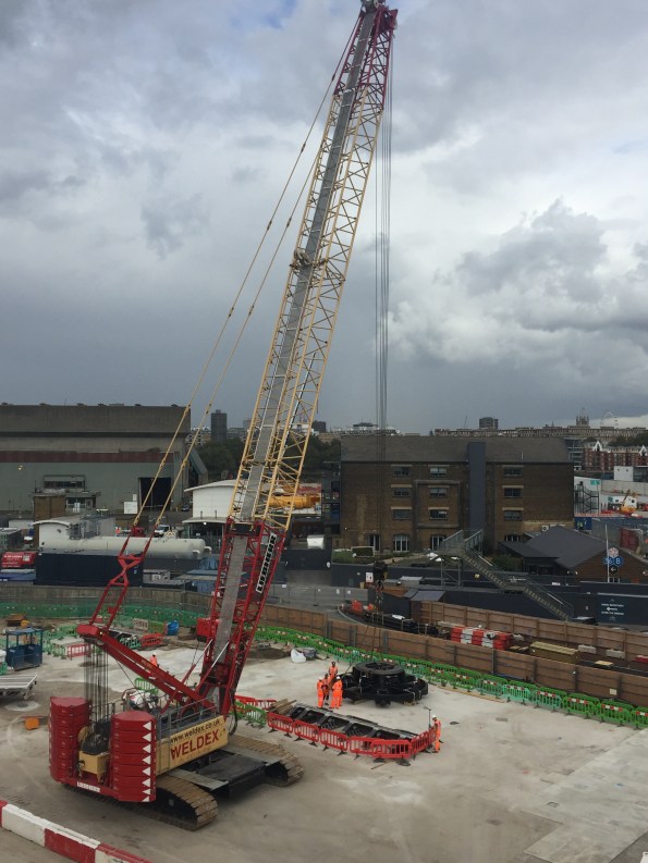
1/ Use a 100t crawler crane and get it as close as possible. Then wrap a lifting chain around the cable and use both to lift together. This should add about 15t in addition to the rig.
Risks: very high risk activity using a crane to do something it isn’t designed for. Requires lift plans, method statements. The connection of chains to cables isn’t normal practice (shackles were not an option). Any slip in the cable could cause a potential collapse onto Battersea Park Road.
Impact to project: Least impact on rig if recoverable.
2/ Pay out as much cable as possible and cut all the cables and hydraulic lines from the grab. Then fix the cables through an anchor block to two100t cranes. Use both cranes to lift in tandem to get the grab unstuck, and in turns bring the grab to the surface.
Risks: very similar high risk activity using a crane to do something it isn’t designed for. Requires lift plans, method statements. Additionally
Impact to project: It would take a week or two to re-condition the grab and reconnect with new cables and lines. Lost time to project.
3/ If all else fails, cut the cables and hydraulic lines and bury the grab.
Risks: Safest in terms of H+S.
Impact to project: Despite the significant cost (£350,000) more critically it would take a long time (months) to find another grab. This would have massive effects on the project.
As we left it on Friday evening, the plan was to spend Saturday completing the necessary paper work and risk assessments to prep for option 1 and if not attempt option 2. The site was open on Sunday which suited as it would be quiet. In the end on Saturday morning the sub-contractor re-programmed or ‘re-baselined’ the software on the rig essentially telling it that it had a shorter jib allowing it to pull harder. It worked…
Why?
Now that the storm has passed there doesn’t seem to be any effort into working out why this happened. I calculated that at the depth that the grab was at, that the bottom 5m was in Thanet Sands. These are fine granular sands that are very hard (SPT tests gave an N value above 50, during some borehole testing we did across the site). I assumed that if stuck in the sands that the ground would tighten with time. or that continued pulls would only make the situation worse.
Has anyone seen anything like this before? We were lucky in this case as all the options presented significant risks. I never got to review the method statement or see the lift plan but if something had gone wrong I don’t know if the measures would have justified the risks.
Apparently Skanska got a grab stuck whilst in the Netherlands. Apparently the Belgian PC was preparing to send divers into the bentonite!!!
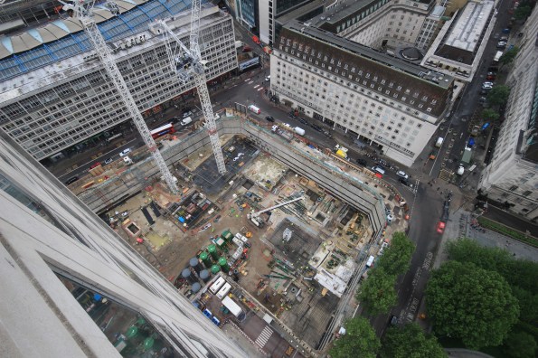
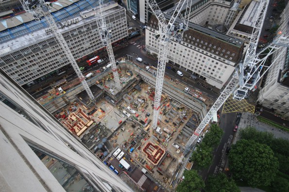
On a different note. The first bit of TBM has started arriving onsite.
Cutter head number 1 and the 250t crawler crane to unload the TBM bits as they arrive
EXCAVATION MADNESS
In my 7.5 months on site I have seen plenty of suspect activities been undertaken by one of the many sub-contractors. In almost every occasion so far the perceived risk to life has been reasonably minimal. In these instances we have had opportunity to discuss the problem with the senior construction team and multiple engineers of varying experience employed by the project.
This morning however, whilst conducting a check of some works on another part of site, I spotted a section of works that concerned me to such a degree that it caused me to cancel everything I was doing in order to have an informed debate (It turned into an argument) with the sub-contractors on-site engineer.
Now I am happy to be wrong, particularly with Geo-technic stuff, but the image below triggered some long archived memories of a JM lecture back in PEW. We effectively have two primary issues that concerned me:
Issue A: Workers operating in a deep unsupported excavation in stiff blue clay. In the worst position the walls were over 2m tall and near vertical. This was compounded by numerous enormous diggers moving around the perimeter providing a particularly unhelpful surcharge.

Issue B: In the background you can see a very, very large stockpile of disturbed excavation material piled up directly adjacent to this work area. This pile must be at least 7m tall and was worryingly close to where the guys were working in the base of the excavation. If that slipped I have no doubt it would end up in the base of the excavation. Given the amount of spoil involved it would take us days to find people under that heap.
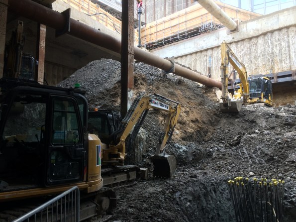
The sub-contractors on site gave me a load of excuses about the stiffness of the clay. I asked them who knew how long it would stand up for, he couldn’t answer. He then told me he was allowed a 1.35m vertical wall (Not sure where that has come from) before it became a problem. I quite quickly pointed out that unless all of his men are unusually short the wall was still well over that limit. I am 185 CMs tall on a good day in my boots (As generously stated on my MOD 90) and it was definitely taller than me.
In the end the answer was simple. It didn’t look right and I knew enough from PEW to have the confidence to stop work until we had some answers. I told them to prove I was wrong and that the excavation was safe in that condition and I would allow them to recommence work. They obviously couldn’t so are now working to make the area safe before anyone else enters the excavation. I also got the temporary works engineer to confirm he agreed with me and funnily enough he did. In summary, when programme comes under pressure expect sub-contractors to cut corners. Alarming but true.
Here’s a conundrum…
Did somebody order the spinning loading platforms???
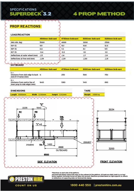
Preston Hire – ‘count on us’.
Progress at Southbank Place
In an effort to convince everyone that I am in fact not working in a deep hole under the Stirling lines I have decided it is high time I blogged to give everyone an update on my project at Southbank Place with Expanded Ltd.
When I last blogged we had just poured the first segment on the basement raft slab. This incorporated a tower crane, drainage runs and sumps, earthing and lightning protection and a lot of concrete. Since then there have a further 27 pours for the basement raft slab using over 7000m3 of concrete and over 1000 tonnes of steel. The basement team (of which I am part of) are responsible for taking the buildings from level -3 to ground, after that the superstructure team take over. The raft slab is 1250mm deep whilst the floors above are 300mm suspended slabs. We have gone from the raft slab on level -3 all the way to ground level on 3 of the 7 buildings being constructed and are now stating the raft slab for the next building. Concurrently to all of this the slipform team have completed the cores of the buildings and are now waiting for the raft slab of the next building to be completed.
The site in May. One pour completed, a tower crane up and works continuing in other areas.
By June there have been another 6 raft slab pours and another tower crane erected
July: more cranes and concrete. You can see the slip form teams preparing the cores for ‘slipping’
August: Slips have stated and basement levels -2, -1 and ground are starting to be finished. -3 raft slab is complete.
September: Ground level nearly complete and slips almost at full height.
Along the way there has been many trials and tribulations as the project has been pushed forward at a relentless pace. The construction manager has a plan on how the project will get built which, a lot of the time, differs largely from the project programme. As a result no one actually looks at the programme anymore, everyone just waits to hear what the construction manager wants to do one week to the next….it is his way or the highway. Even the senior project managers bow to his every command and go with whatever he says. I find this a very odd way of going about business but the project is going forward at a rapid rate so it obviously works. There has also been a high turnover of engineering staff on the job. Out of a team of 12 engineers there are only 4 (myself included) that are still on the job now. I personally think the high turnover is a product of the ‘unique’ management style but I may be wrong.
Other issues that have been encountered include ‘feeding the beast’. This is the process of making sure there are enough materials (rebar, waterproofing, drainage, etc) on site for the workforce so that there is no delays to the project. Whilst this seams incredibly simple it is surprising how often you will only get told when they run out of equipment….never when they are just running low. They are all aware that they just have to use the materials, not order it. I’m sure that everyone else has this issue and is equally frustrated by it.
During my time on site my role has moved from being the senior engineer on the -3 raft slab (now complete) to managing the handover package. This involves directing the ‘making good’ team and liaising with the client (Canary Wharf Contractors) in an attempt to handover sections of the basement to them so that further trades can start work. They are yet to take a single area due to a variety of minor defects ranging from small cracks in the slab to plywood being left behind a corner. I think that they are just trying to play hardball on the first set of handovers but if I keep promising them the world and laughing at their jokes I’m sure they will accept the areas eventually.
For any Phase 1’s reading this Southbank Place will still be in full swing when you go to placements in February. Whilst it is hectic and demanding there is a large amount of experience to be gained so if you have never been on a construction site before it could well be the place for you.
On a side note I interviewed for a Phase 3 attachment with Wentworth House Partnership. As part of the interview there was a structures paper…..needless to say it was a bit of a shock to the system. However the office is only 3 miles from my house so I’ll get over it! I will be starting there after I have conquered the slopes of Austria on Ex Racing Ice.
Materials Audit
Following loosely on from the current E&M theme of FATs and SATs I today visited the BP warehouse to check the materials and fabrications for one of my projects. the warehouse is operated by ASCO and located nearby in Dyce. The purpose was to check that the materials delivered matched the requirements of both the BoM and design drawings. The warehouse is pretty much brand new and accommodates both spares for existing platforms and the materials for repairs and modifications. Warehouse pictured below:


Materials are held here and ‘called off’ when required, which involves packing the materials into shipping containers and delivering them by road to Aberdeen harbour where they are transferred by ship to the offshore platforms. Upon auditing the materials for the project in question we found everything to be present and it looked in good order:


Whether the materials reach the platform in the same condition and complete is another matter. Compared to the plant in Stu’s post, the internals are protected from ingress and corrosion with blanking plates. We did however had a look around the warehouse and there were materials (not related to my projects) in a similar condition to what Stu found:

It seems to be down to specification. The blanking plates and protected ends of the pipes and valves are specified by BP and the slightly orange pipework above is likely to be blasted and painted as per BP spec if it ever used offshore. As to the effect on flow of internal corrosion I’m not sure. Maybe a topic for a TMR…
Also of note were the PPE requirements. We required safety boots, goggles, hi-viz and hard hat as a minimum to enter the warehouse. A bit different to the farmyard Stu visited by the looks of it. Even Gary’s hi-tech factory visit seemed to allow a ‘come as you are’ policy. Probably one of the many offshore safety aspects that permeate through to the onshore parts of the business.
The total value of the materials checked was £38,000. Not bad considering they are all custom fabrications to the project specifications and designed to withstand both the offshore environment and the corrosive hydrocarbons they will contain. The value is also a pittance compared to the $2.5 million per week of product which will flow through them.
Ground investigation by method?
On the Paradise Circus site there are a number of different types of foundations:
- Rotary bored piles (900mm and 1200mm)
- Single pile caps
- Grouped pile caps
- Cantilevered pile caps with tension piles
- Ground beams
- Pad foundations
- Ground bearing slabs
- Suspended slabs
The last two are pushing it, but I thought I would throw them in as they are definitely in the future of this project.
I have been asked to investigate a request by the designer that the location of the Pad foundations be subject to a Plate Bearing test (Carillion are obsessed with these and so seems the industry as a whole – has anyone else experienced this?). The plate bearing test has been specified as a must have to us and due to my protests at this, I was given the task of liaising with the designer.
The need for this test is to qualify the assumptions made during design – happy with that. The test must be completed at the formation level of the pad foundation – not happy with that.
Although the pad foundations are nominally 1.2m deep, the formation level is the Sandstone strata that at it’s highest point is about 3.5m BGL. In order to conduct a plate bearing test there needs to be a technician with the equipment and a machine large enough to create the pressure needed on the plate.
Edit: The distance between the bottom of the pad foundation and the rock strata is made up with mass concrete fill (bonkers?)
I conducted a similar test on a 450mm dia plate at 550kPa and needed a 22T machine to Jack-off – this test has been specified to 1500kPa. Here is a photo of the former.
Take in to account the excavation to 3.5m depth and a safe batter of 1:1.5 (Carillion standard for large excavations) and the requirement to do about 10 of these over the site – we’re looking at basically doing a reduced level dig to the sandstone across the site.
Now I have asked the question “What do you want to know, Mr Designer?” As I said previously, the aim is to qualify the assumptions made during design – these are regarding settlement. The designer has come back at me with “Stiffness”.
I now need a method of finding the stiffness of the sandstone between 3.5 – 10m depth across the site – without excavating enough material to fill Wembley stadium. I have made some suggestions but will keep these to myself for now – what would you have said or come up with?
BIM induced delays
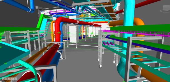
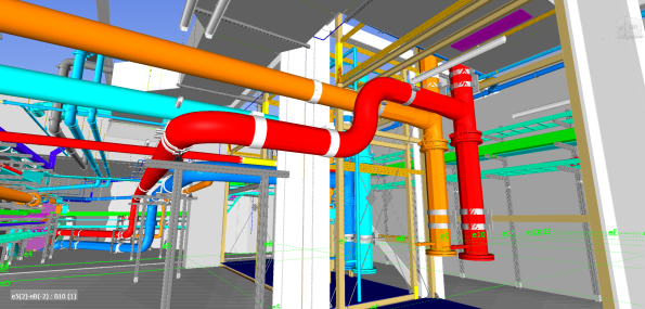
I am responsible for the fitting out of a basement area and so I am trying to sequence the works, using the BIM model to decide the order in which stuff needs to be installed. As such my works programme is becoming pretty complex. Here is a 3D BIM model of the area I have to fit out including all pipework, ladder racks, trays, ductwork and basketry. This task will involve the management of six separate sub-contractors and their interfaces.
BIM is a great tool but very slow and I am finding that the constraint on when I can start each work package is not the supply of materials or availability of sub-contractors but rather the production of construction drawings. So now we are at the point where the drawing production programme is driving and dictating the MEP programme. Due to a lack of coordination at the start of drawing production, the drawings are not being produced in the sequence of construction, causing further delays in several areas and messing with my programme. We have now coordinated with the BIM Team and created a drawing sequence that better reflects what we plan to do on site.
Is this issue unique to our site or common place where BIM is the primary driver of the Building design?
Here is another pic of the basement area showing the complexity of the task:
Sadly, I will not be able to finish the fit out of this area before departing the project and so will not be able to install the whole of the ductwork, smoke extract system, fire alarm system and most of the cable racking.
Factory Acceptance Testing
Like Stu I have recently been involved in Factory Acceptance Testing (FAT) testing but rather than spending a day on a dusty farm, I attended one at the Carrier Test Facility in Lyon, France.
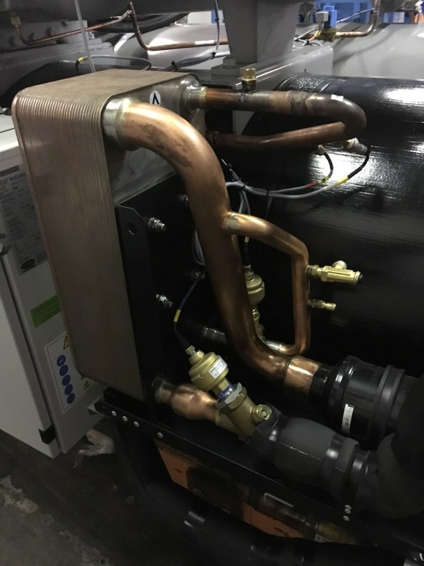
The FAT visit involved witnessing the testing a variable chiller unit. It was a very useful visit as it meant revisiting the refrigeration cycle and learning more about how chillers are constructed. It also included a nice hotel and slap up meal fully paid for by the Client! Here is a picture of the Chiller being tested:

The Chiller is a 1713kW single stage chiller that uses R134A refridgerent and has a Coefficient of Performance (COP) of 4.56. As you can see from the picture, it is in fact two identical chillers bolted together and these two work in parallel and not as a two stage refrigerator. This type of chiller gives better performance at low loads as only one side will be ran. In the picture, the grey cylinders are the condensers and are basically large tube heat exchangers. The condensate is circulated through a closed loop system (45degC flow and 35degC return) that sees it either sent to the cooling towers, heating system or to the boreholes (this system is fully controlled by the building management system being designed by Honeywell). When running at full load, the system provides 2.08kW of heating. The large items on the top are the compressors and the large black insulated cylinders at the back are the evaporators and supply chilled water at 9degC flow using a 14degC return.
Of particular interest was the economiser which I admit struggling to understand fully in Phase One. So here is a picture of an economiser:
As I am sure, all of the E&Ms will remember that the economiser is used to create Sub-Cooling in order to improve COP. It works by diverting some of refrigerant leaving the condenser and then throttling it to the reduce the temperature. This colder flow of refrigerant is then used to sub-cool the main flow using a Plate Heat Exchanger (PHX).
To understand this system, I used a free to download programme called CoolPack. This program allows you to easily plot P-V and T-S diagram and conduct refrigeration calculations. I recommend this program to all E&Ms.
As part of the testing schedule, the chiller was ran and full, 75%, 50% and 25% load. Each time, the chiller was left for 30-45 mins to allow it to stabilise to a predetermined tolerance. Then the system was ran for a further 30mins and the temperatures and pressures were measured and plotted as shown below:
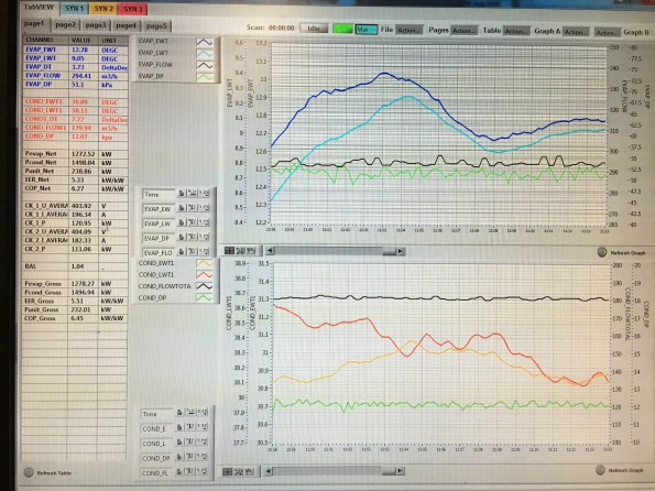
For each test to be signed off as acceptable by us, the chilled water supply and return and condensate supply and return had to be within a tolerance of the design temperatures. Also we checked the power consumption of the system, the heating and cooling outputs and COP for compliance. The Chiller passed all of these tests.
The final part of our testing schedule was to test fault conditions. To do this we increased the system pressure, simulated a loss of power and shut off the cooler pump to simulate a lack of water flow in three separate tests. For each of these tests we reviewed the chillers response such as instantly stopping, allowing the pressure to equalise across the compressor and the messages displayed on the Human Machine interface (HMI). The Chiller reacted correctly in all of the tests but during the high pressure test, one side shut down correctly and displayed the high pressure fault code but the other side shut down but displayed an electrical fault code. So we asked for the test to be ran again but for the faulty side to be ran on its own and this time it displayed the correct fault code after tripping. We also provide carrier with some requests as to how to better display messages and the visual layout of the SCADA system on the HMI.
This proved to be an excellent trip and opportunity to experience FAT testing. It also turned into a very useful refrigeration revision session!
I am hoping to do my next FAT trip to Austria next month and so look forward to a similar blog…….
Any ideas for removing props when stressed?
I am currently trying to build my way out of the 22 m hole I have dug for myself in South Brisbane. Progress has recently accellerated now that the excavation is over. In the last 3 weeks the structure has completed Basement levels 6, 5 and 4. we are currently at Basement level 3 and in the next week we will be at the same level as the props (Basement level 2), which presents some challenges. The props are significant pieces of engineering and consist of 900, 752 and 508 mm Circular Hollow Sections in each corner.
In order to keep the job moving we will have to remove two of the props that clash with the permanent structure (highlighted) and build over the remainder. This flies in the face of conventional wisdom but, lets focus on the problem at hand. The removal of these props is potentially very hazardous, since they were installed the wall has deflected inwards by up to 26 mm and as consequence the props could potentially be under 2-3 MN of compression.

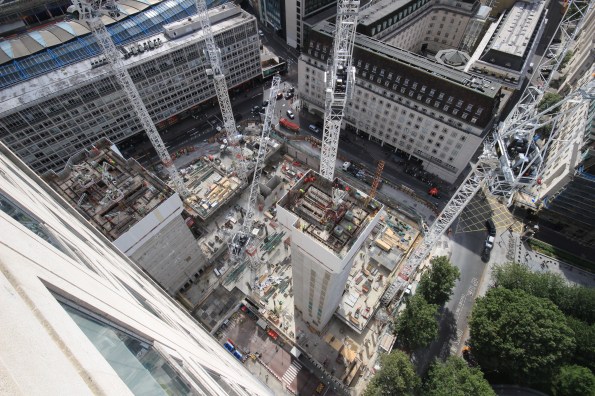
Aerial photo taken of site (this was taken 3 weeks ago when we were on Basement 6)
Having just received my sub-contractors method statement (similar to how a lumberjack would cut down a tree). I concluded that they will kill someone so I have consulted the ‘hole diggers bible’ (CIRIA 517). Unfortunately, the struts are welded in to the walers so it removes a lot of potential options. I believe the only method left to follow is to cut progressively larger holes in the CHS while supporting them from either the deck or the tower crane.
Given that the deck will just have been poured and would require propping all of the way down to Basement level 6, I am reluctant to recommend this option. The sole use of the tower crane is equally unpalletable but, if it was conducted at a time when the majority of the site was empty it could work. I am open to any better ideas though.

Access. The props will block access around the site, so I have had to ask our scaffolders to build an access way on top of the walers. Unfortunately ladder access is frowned upon, so I have found some safety stairs that will be able get from the working deck to the temporary scaffold access. The safety stairs will be used in areas marked in yellow (above) that cannot be accessed by existing the existing stairs. We tested this on site today by placing them against the existing scaffold stairs.
Things are about to get very messy – I think its time to go on leave.
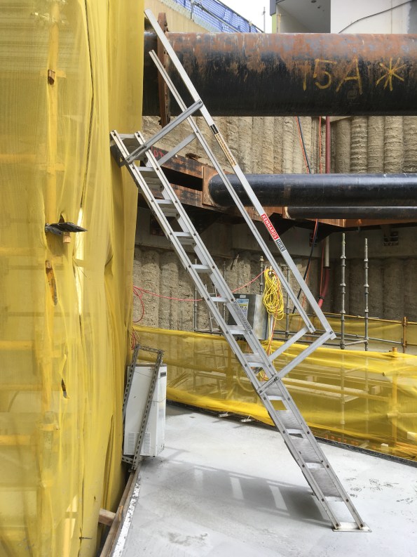
They are getting closer! -Photo taken from Basement level 3 of safety stairs against , props and walers in background (note we have built over the ground anchors now).
