Archive
Modification of post tensioned concrete: update…
In my last blog I explained how I was planning the modification of an existing post tensioned slab, here is a quick reminder…
For unknown reasons the ground floor slab of an adjacent building cantilevered into our site by approx 2m. As we are building a bottom-up 4 level basement, this intrusion obstructed progress.
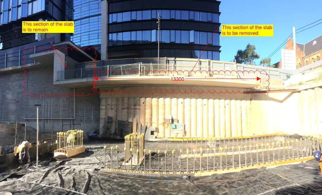
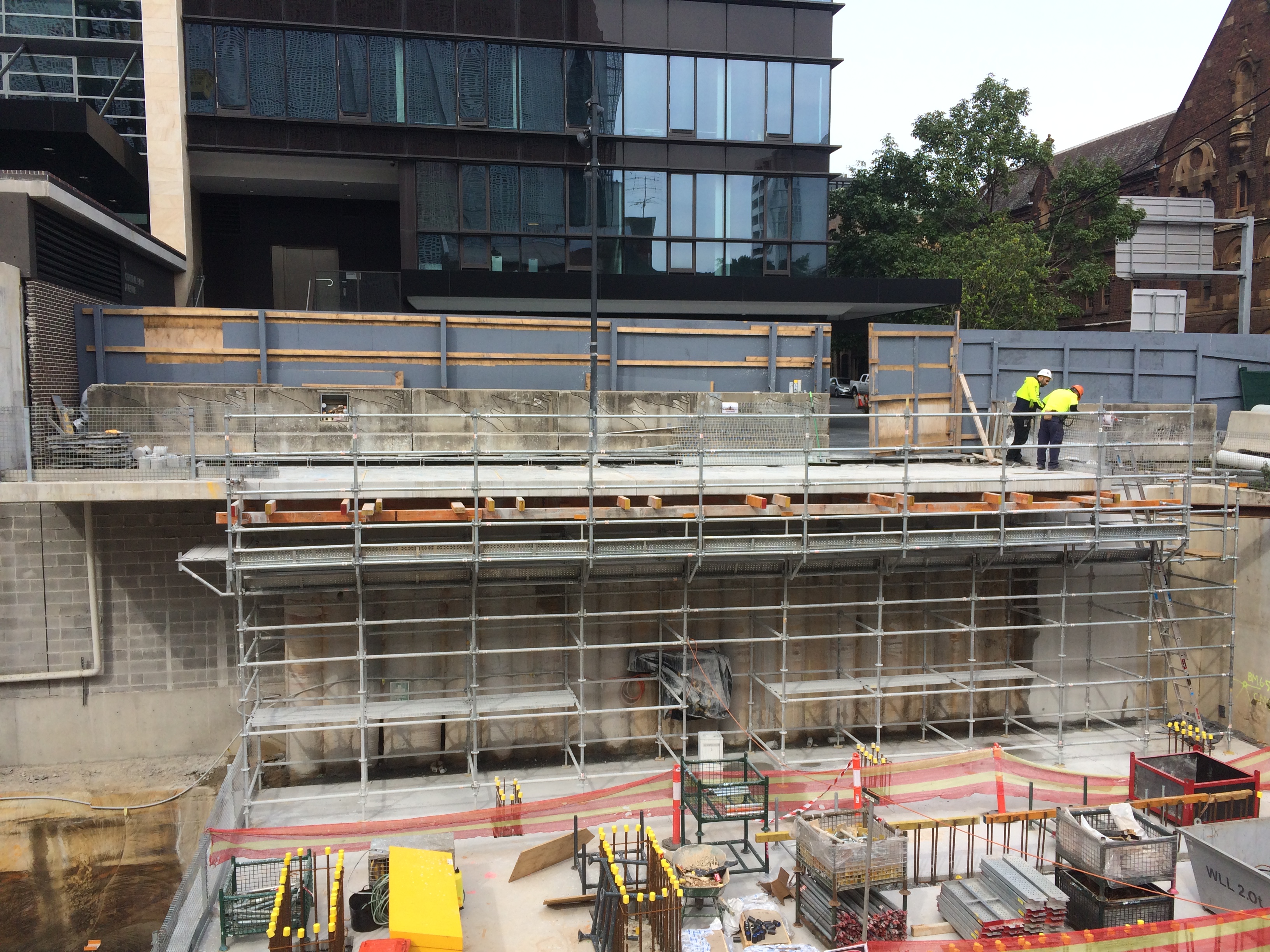
Step 1: In order to remove the offending section (2m x 14m, 250mm thk), we first analysed the likely effect on the remaining slab. This was anticipated to be between 2 and 5mm – acceptable. Step 2: We constructed falsework to the underside of the section being removed to allow the section to be temporarily supported between being cut and lifted out. This falsework also provided access for the crane crew and edge protection during the cutting process.
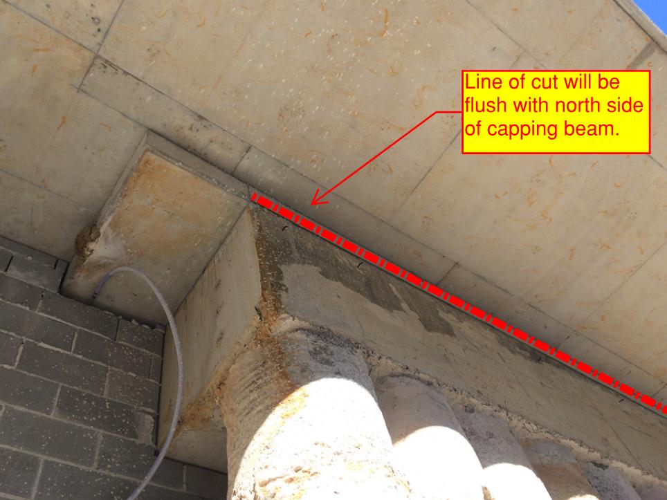
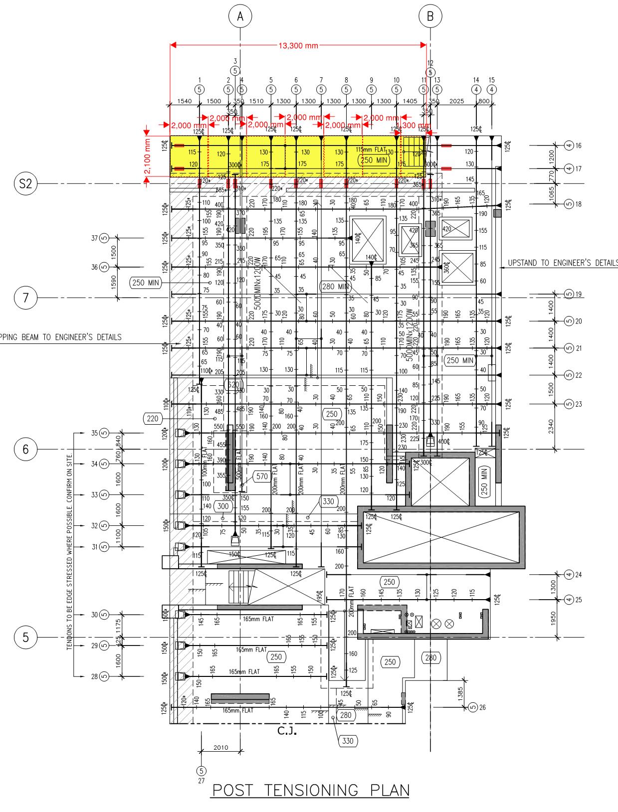
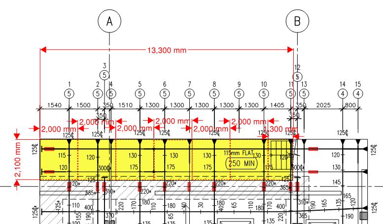
Step 3: We scanned the area to locate services and ensure PT ducts were as per the as-built drawings, they were. Step 4: Truncate the PT tendons 100mm past the line of cut (in the section of the slab remaining) to ensure the tendon remains stressed once the cut. The image below shows the entire slab, the section removed is highlighted yellow, the red rectangles represent areas of the PT duct which were truncated. A more detailed image is below it.
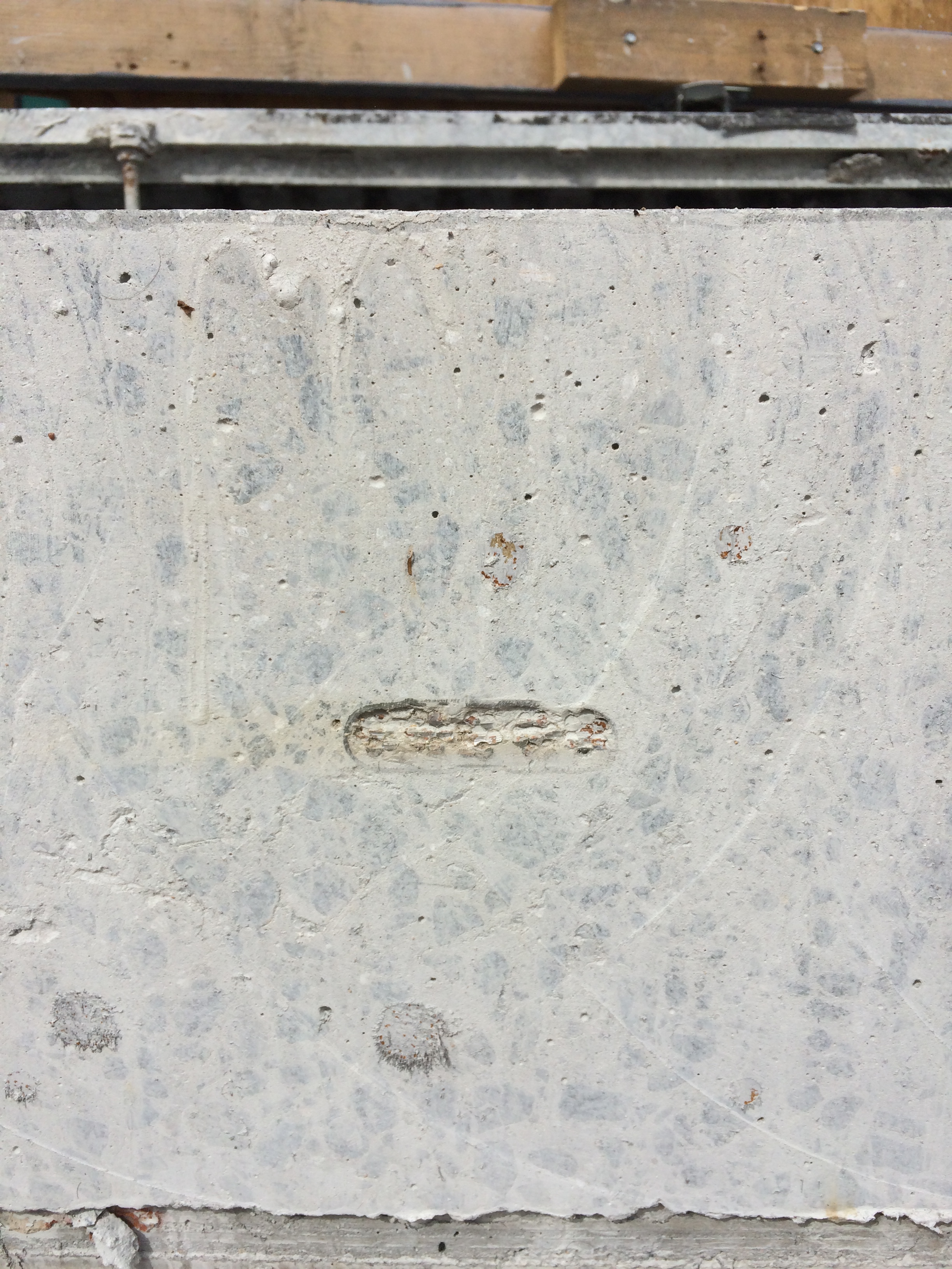
The truncation process involved removing a 500mm x 200mm by 150mm deep section of the slab to expose the PT duct, image below. The duct was then stripped back to allow inspection of the grouting around the tendons. The void was then filled with an epoxy which, once cured, acts as a plug to truncate the remaining tendon.
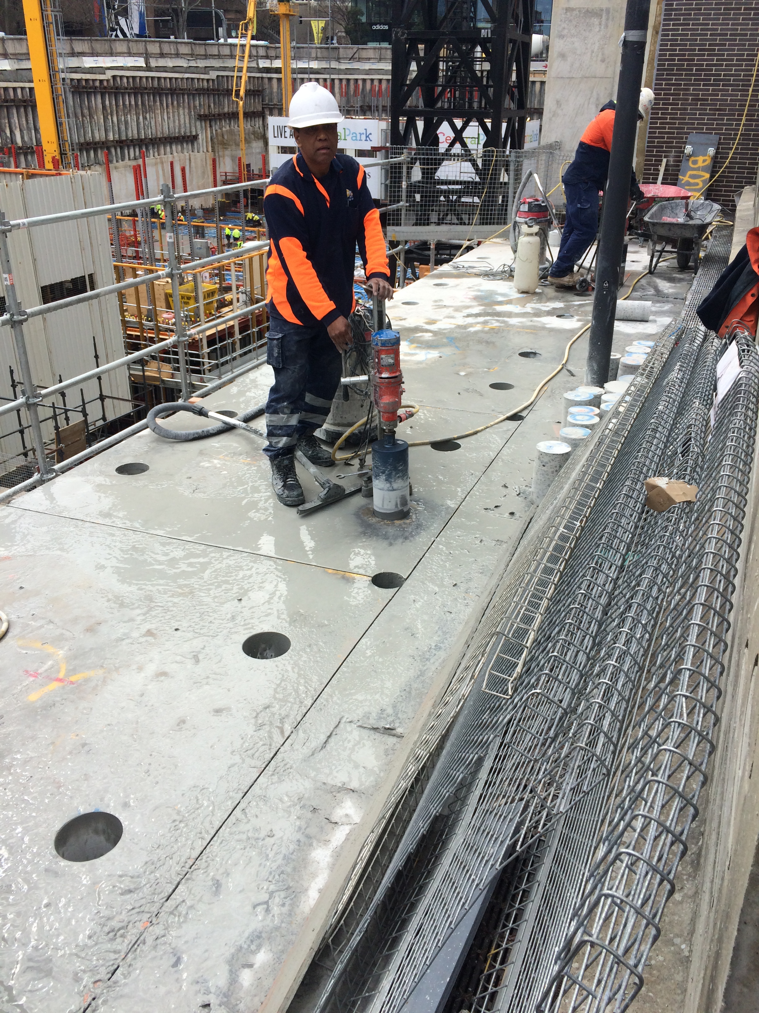
Step 5: Core holes were then drilled for two reasons… 1. to allow the sections to be slung by the crane crew, 2. to prevent the ‘road saw’ from over cutting at key locations.
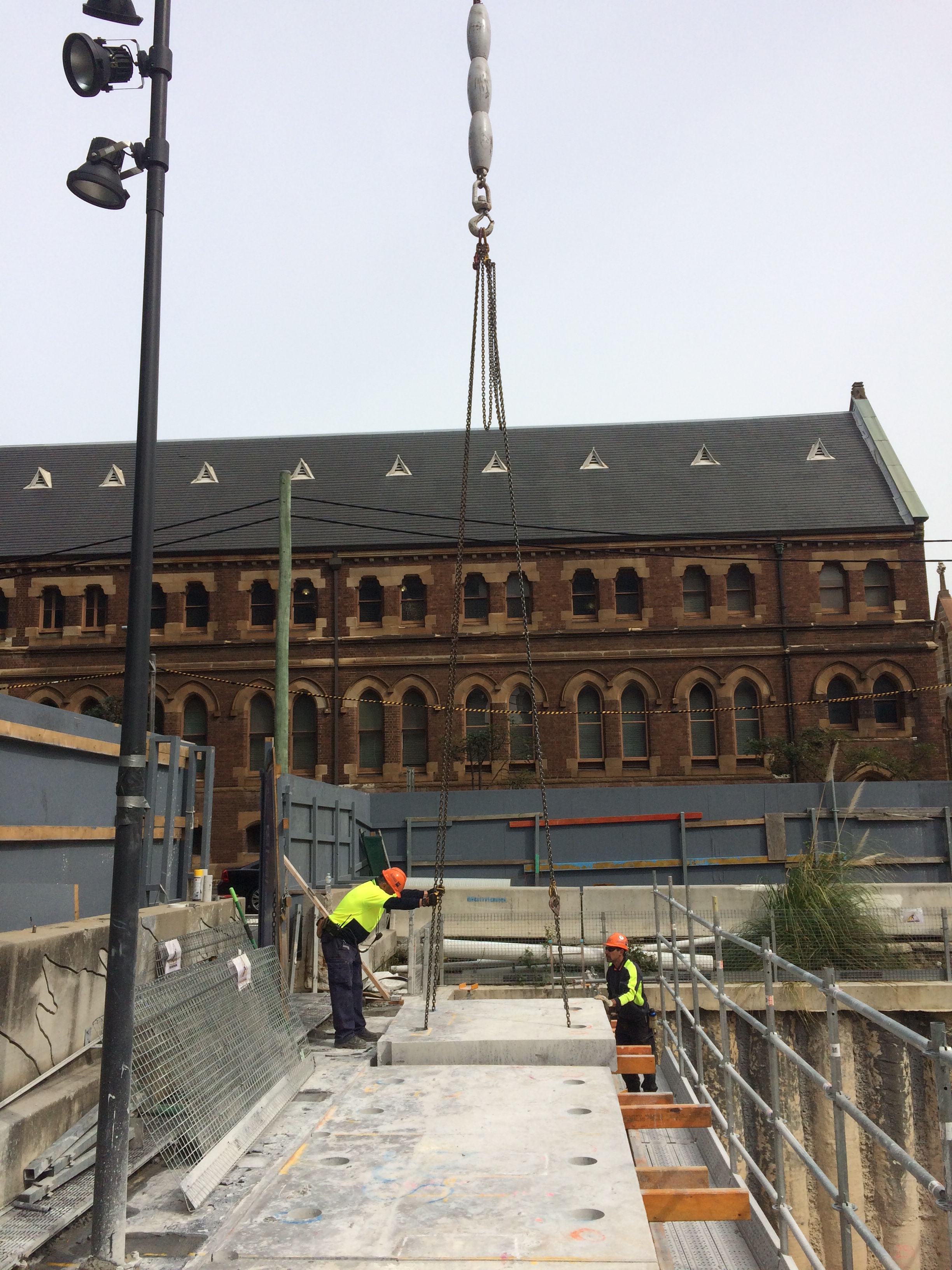
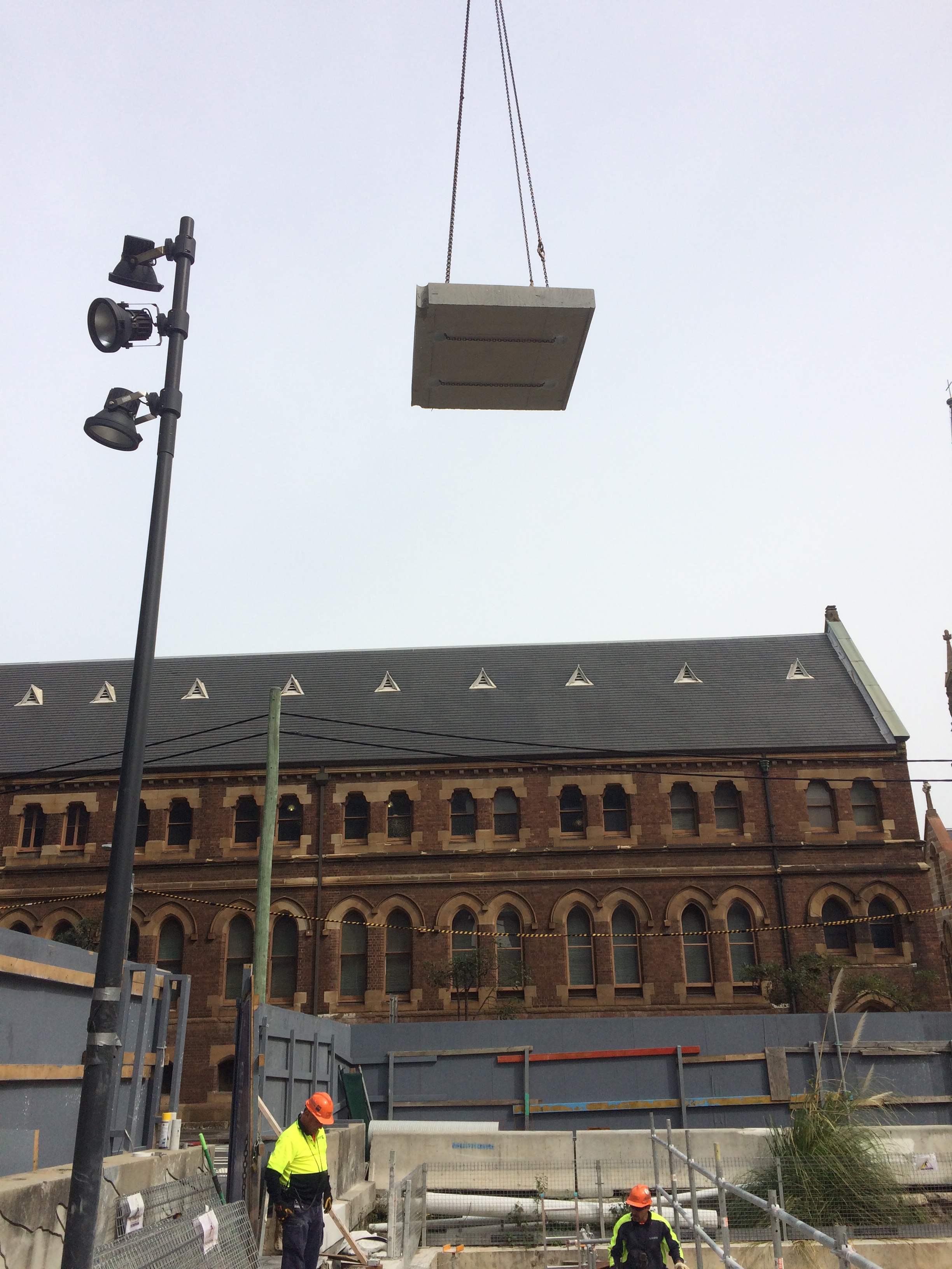
Step 6: The sections were then slung and lifted out for removal from site.
The final step involves treating the newly exposed PT tendons to prevent corrosion. On inspection we noticed that the PT tendons had slipped at 2 of the 12 epoxy plugs, one by 70mm and the other by 180mm. Initial analysis indicates that the slip is acceptable but an investigation is ongoing to work out why the slip occurred. In my opinion, it is worth noting that these two locations lacked grout around the tendons during the grout inspection. More is therefore being asked of the these epoxy plugs. It is also worth noting that the epoxy didn’t appear to be completely cured. In my opinion, these two factors are to blame for the slip, but hindsight is a wonderful thing and time is money apparently…
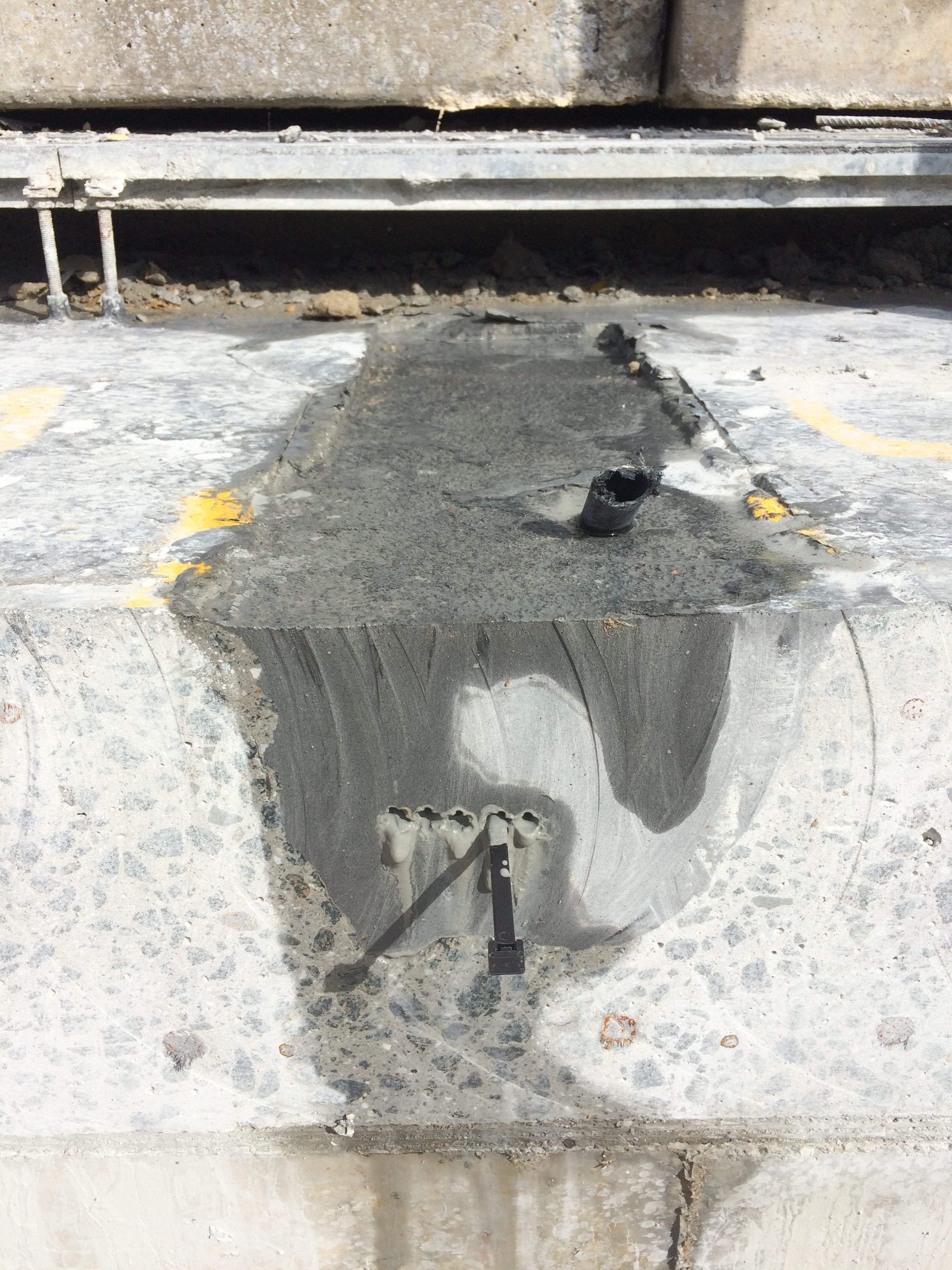
The image below shows the exposed PT tendon at the face of the cut. NB: no slip!
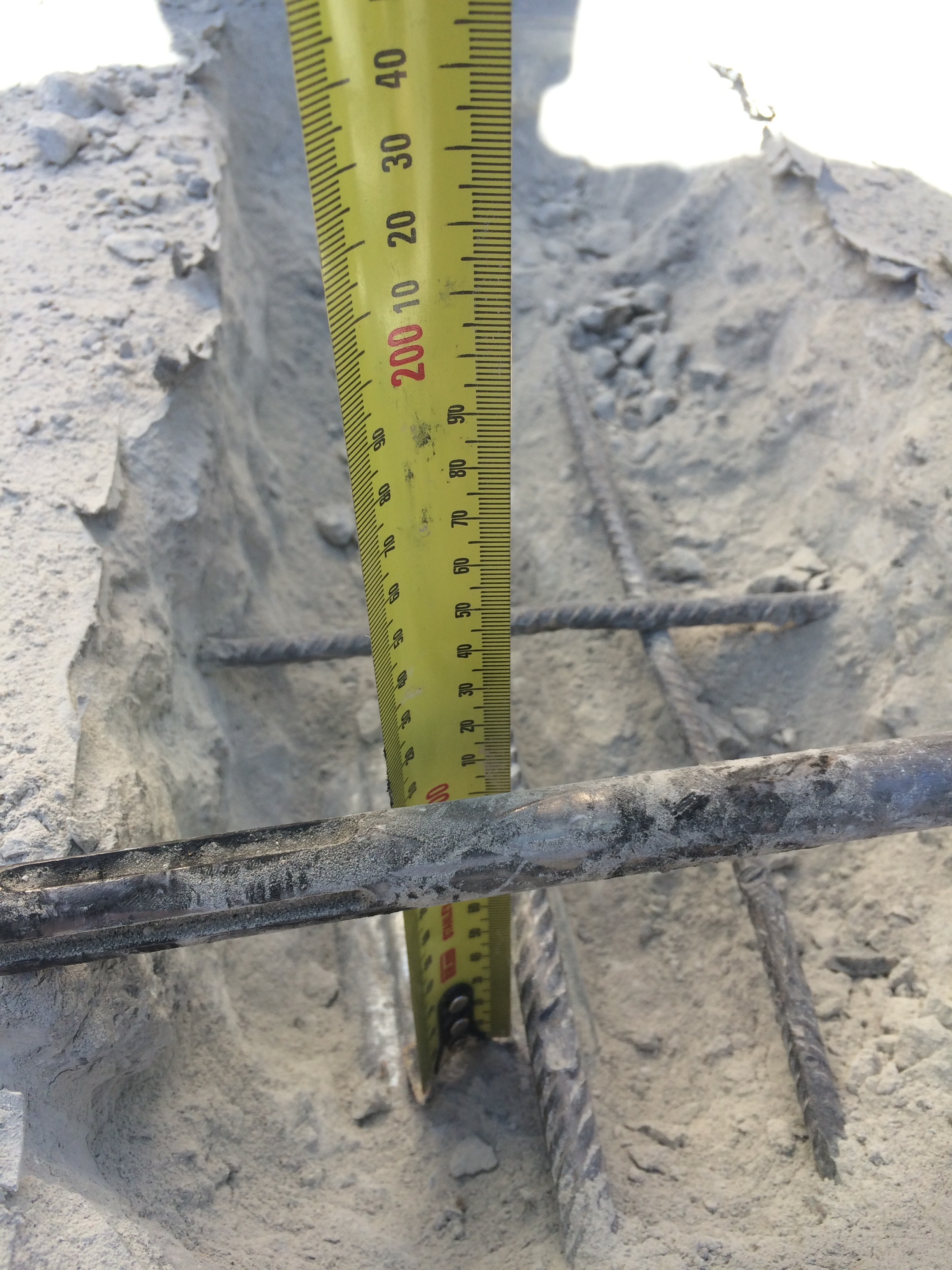
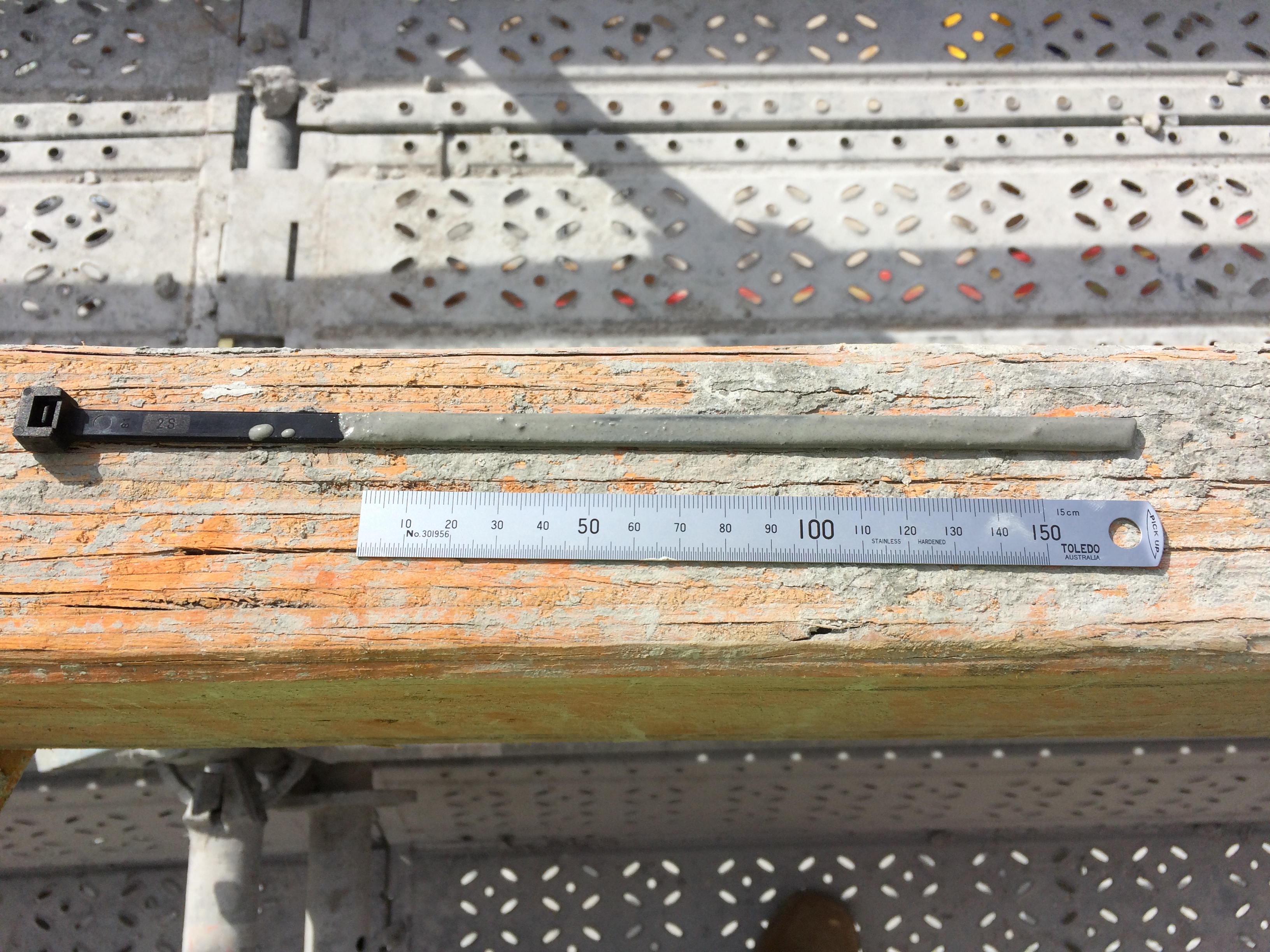
The image below shows slippage of the PT tendon at the face of the cut. NB: my high-tech cable tie measuring device!
More to follow…
Battersea Power Station Phase 3 Update
I realised I have been a blog voyeur and not participated a great deal so I thought I would provide an update.
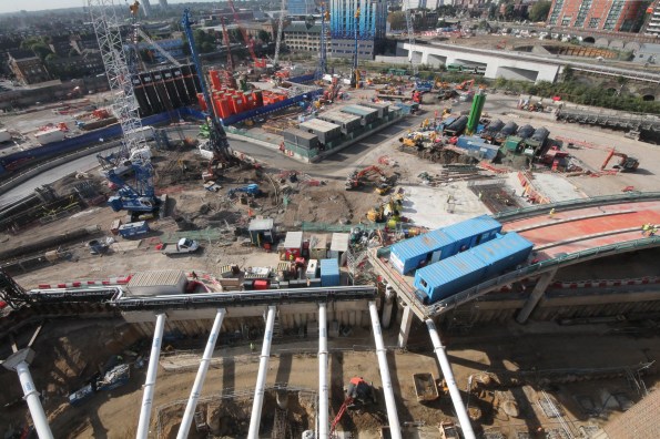
Photo 1 – Site today.
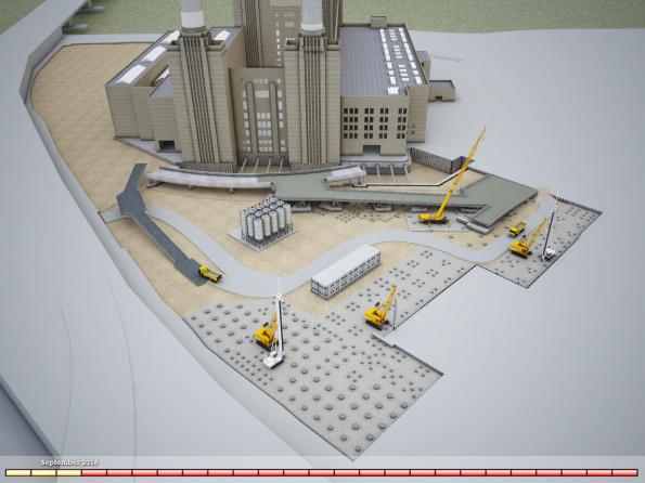
Photo 2 – My task – Bridge 1 CAD image (NB existing ramp visible on left. The existing ramp is visible from the train when travelling into Victoria).
Balfour Beatty Ground Engineering has nearly completed all piles (nearly 300) along the line of the first temporary bridge structure (area A). This has allowed McGee to commence construction of the pile caps that the bridge structure will sit upon. Points of note. Photo 3 shows Dolphins 7, 8 & 9 (the terminology for the RC sway frame that the bridge steel decking sits upon). The pile cap for dolphin 9 has been poured, the rebar for dolphin 8 is being fixed and the blinding has been poured for dolphin 7. There is over 140m^3 of concrete in the pile cap and when the excavation commences this pile cap will sit approximately 13m above formation level.
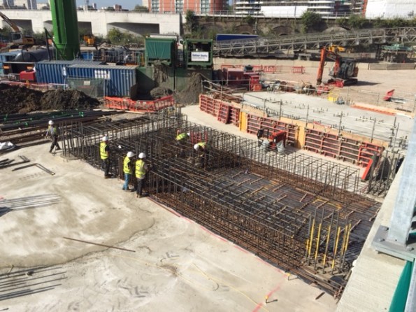
Photo 3 – View of ‘Dolphin’ 7, 8 & 9 with pile cap 9 poured, rebar for pile 8 fixed and over 40m^3 of blinding for Pile cap 7.
In tandem DAM structures have commenced fabrication of the steel deck structure and I have conducted a number of visits to East Yorkshire (‘Brid’ as the locals call it). All of the sections are ‘standard’ road haulage dimensions to avoid wide loads. The bridge deck comprises three 2.4m wide sections plus edge sections – Photo 4 shows a standard bridge deck on its side in order to weld the steel plate that makes up the road surface.
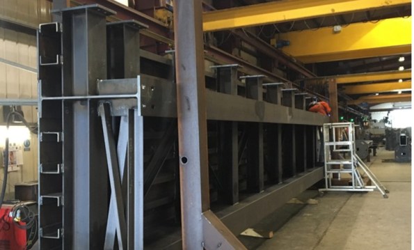
Photo 4 – Steel Deck Sections in the fabrication shop (This is a ‘normal’ deck section 2.4 m wide, 12m long and weighs approx. 13T) .
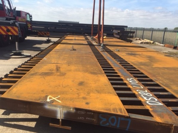
Photo 5 – Practice lift and erection in DAM Structures yard (these are special deck sections that connect to the existing permanent bridge).
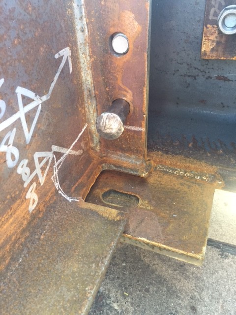
Photo 6 – Connection detail.
Interesting ‘stuff’ going on:
- Contractual wrangling is still on-going.
- Bouygues UK has not signed a contract and is moving toward a construction management role.
- BBGE has not signed either
- McGee has finally signed on the dotted line.
- We had a spate of safety issues but they pale into insignificance compared to Kukie so I will not bore you with them.
- Too many piling issues to mention from pile rig failures through to changing ground conditions and everything in between.
Bit of a long post – apologies James!
