Modification of post tensioned concrete: update…
In my last blog I explained how I was planning the modification of an existing post tensioned slab, here is a quick reminder…
For unknown reasons the ground floor slab of an adjacent building cantilevered into our site by approx 2m. As we are building a bottom-up 4 level basement, this intrusion obstructed progress.
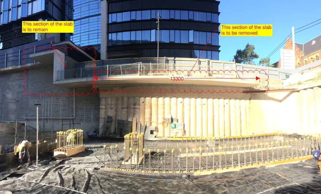
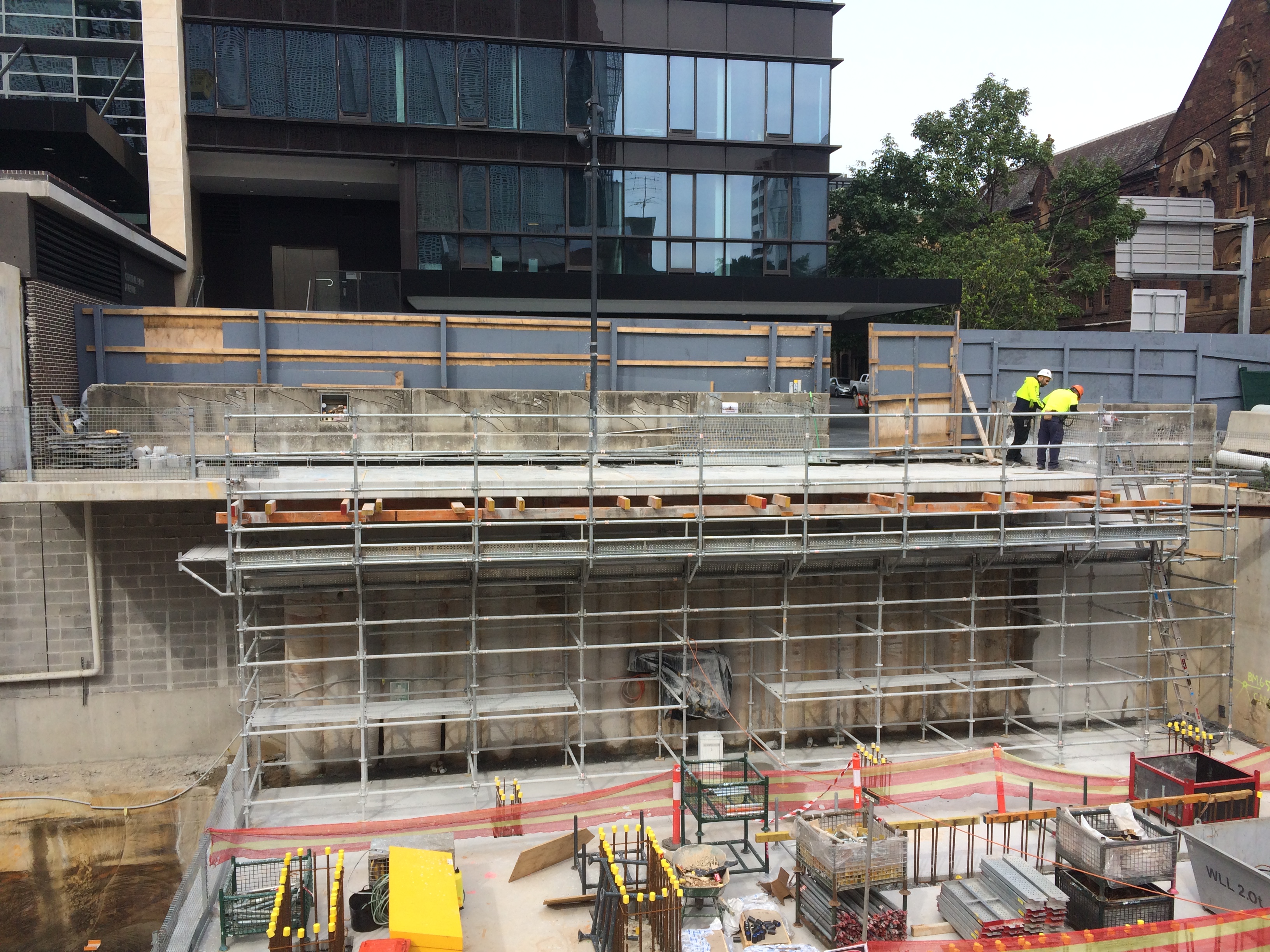
Step 1: In order to remove the offending section (2m x 14m, 250mm thk), we first analysed the likely effect on the remaining slab. This was anticipated to be between 2 and 5mm – acceptable. Step 2: We constructed falsework to the underside of the section being removed to allow the section to be temporarily supported between being cut and lifted out. This falsework also provided access for the crane crew and edge protection during the cutting process.
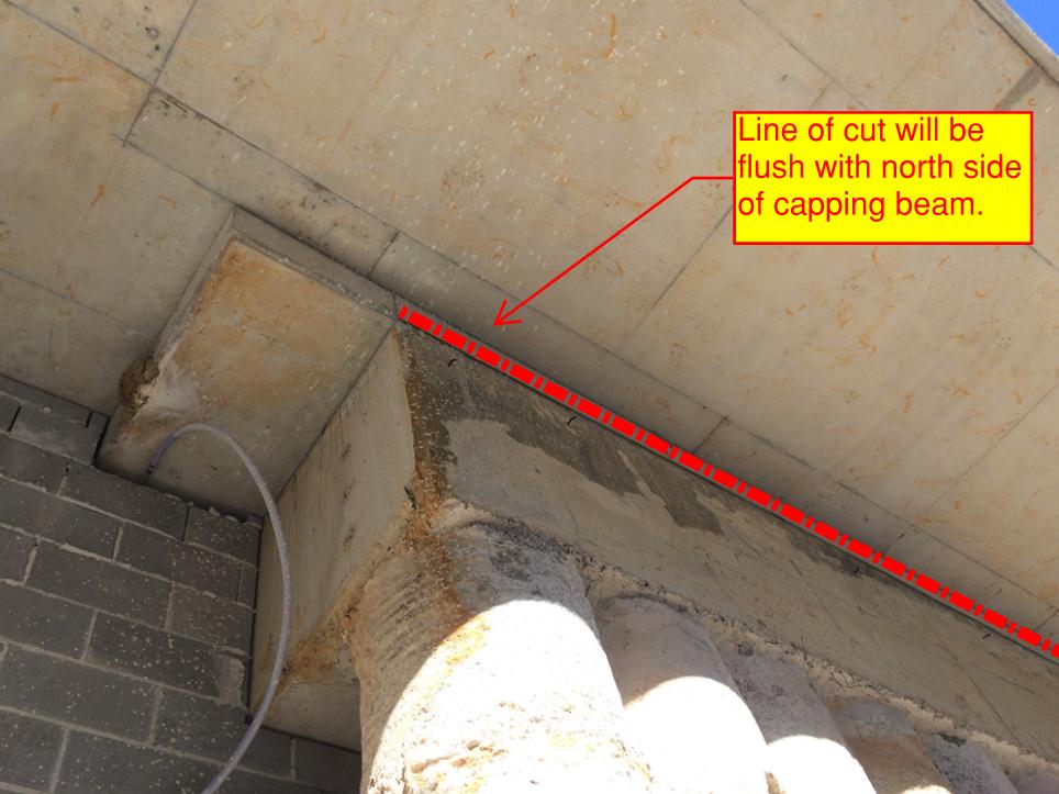
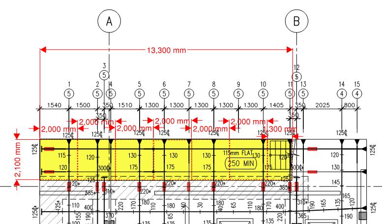
Step 3: We scanned the area to locate services and ensure PT ducts were as per the as-built drawings, they were. Step 4: Truncate the PT tendons 100mm past the line of cut (in the section of the slab remaining) to ensure the tendon remains stressed once the cut. The image below shows the entire slab, the section removed is highlighted yellow, the red rectangles represent areas of the PT duct which were truncated. A more detailed image is below it.
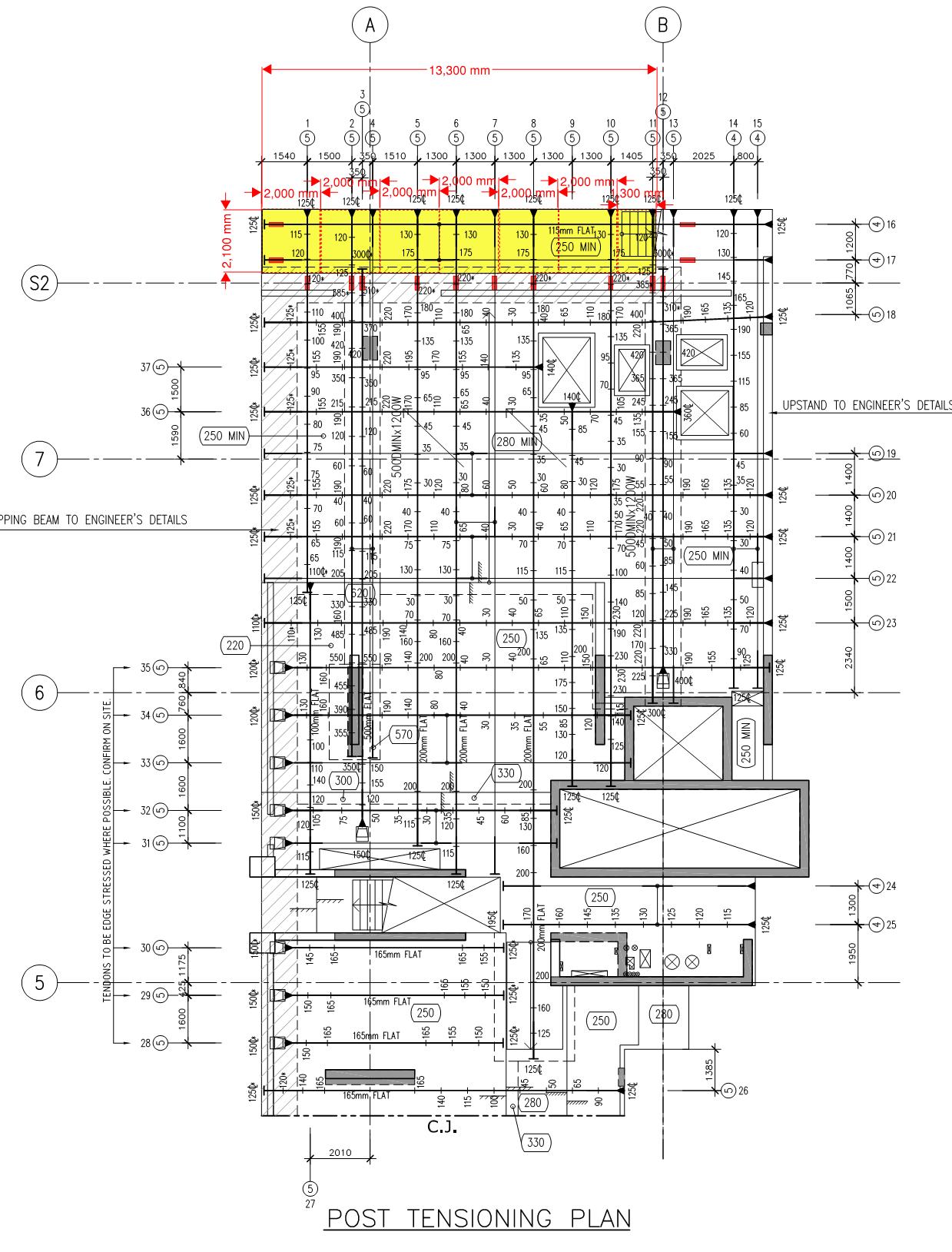
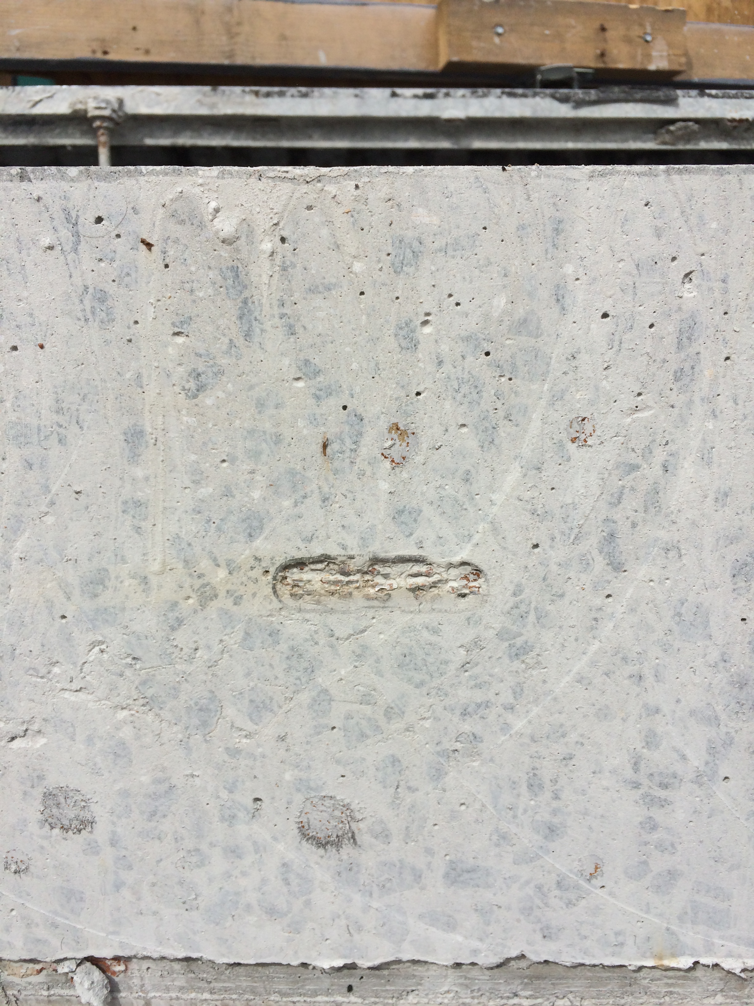
The truncation process involved removing a 500mm x 200mm by 150mm deep section of the slab to expose the PT duct, image below. The duct was then stripped back to allow inspection of the grouting around the tendons. The void was then filled with an epoxy which, once cured, acts as a plug to truncate the remaining tendon.
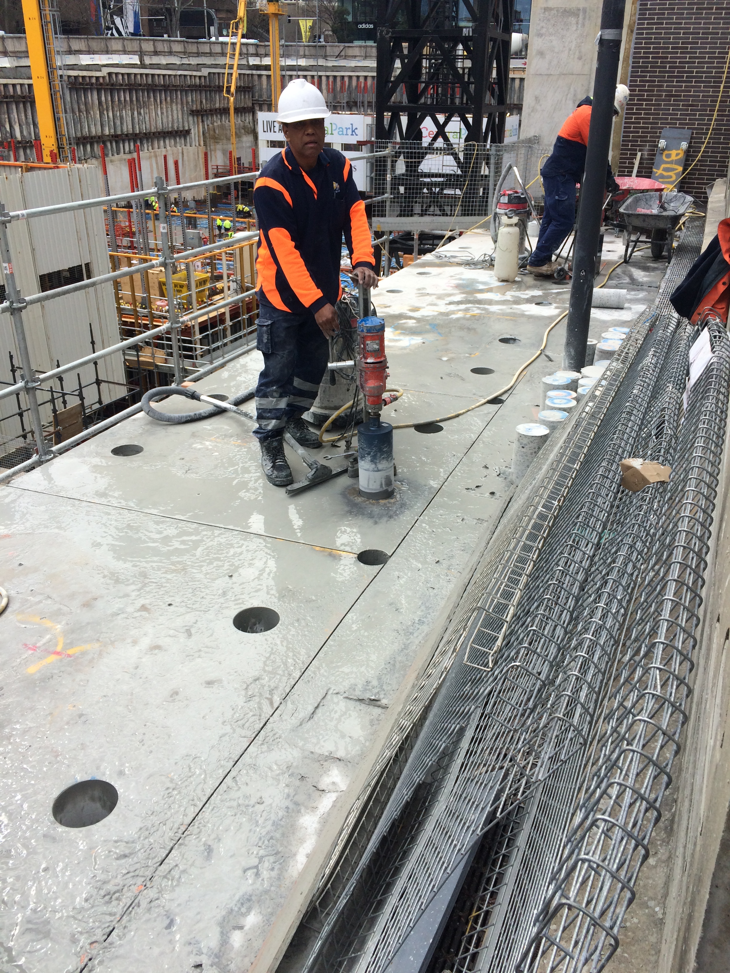
Step 5: Core holes were then drilled for two reasons… 1. to allow the sections to be slung by the crane crew, 2. to prevent the ‘road saw’ from over cutting at key locations.
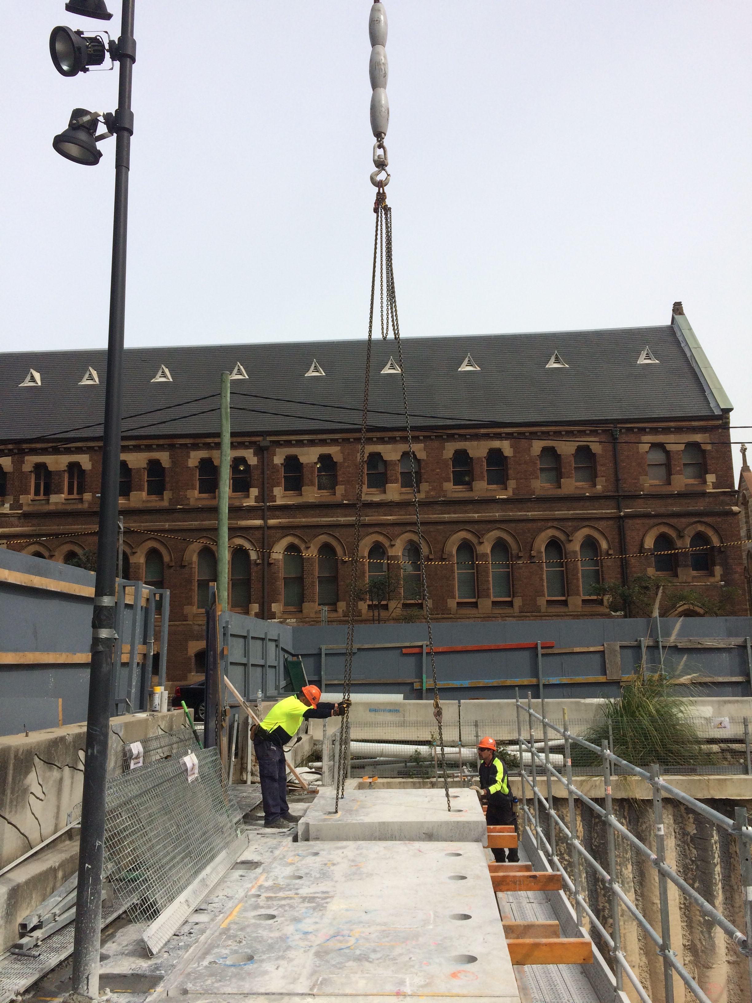
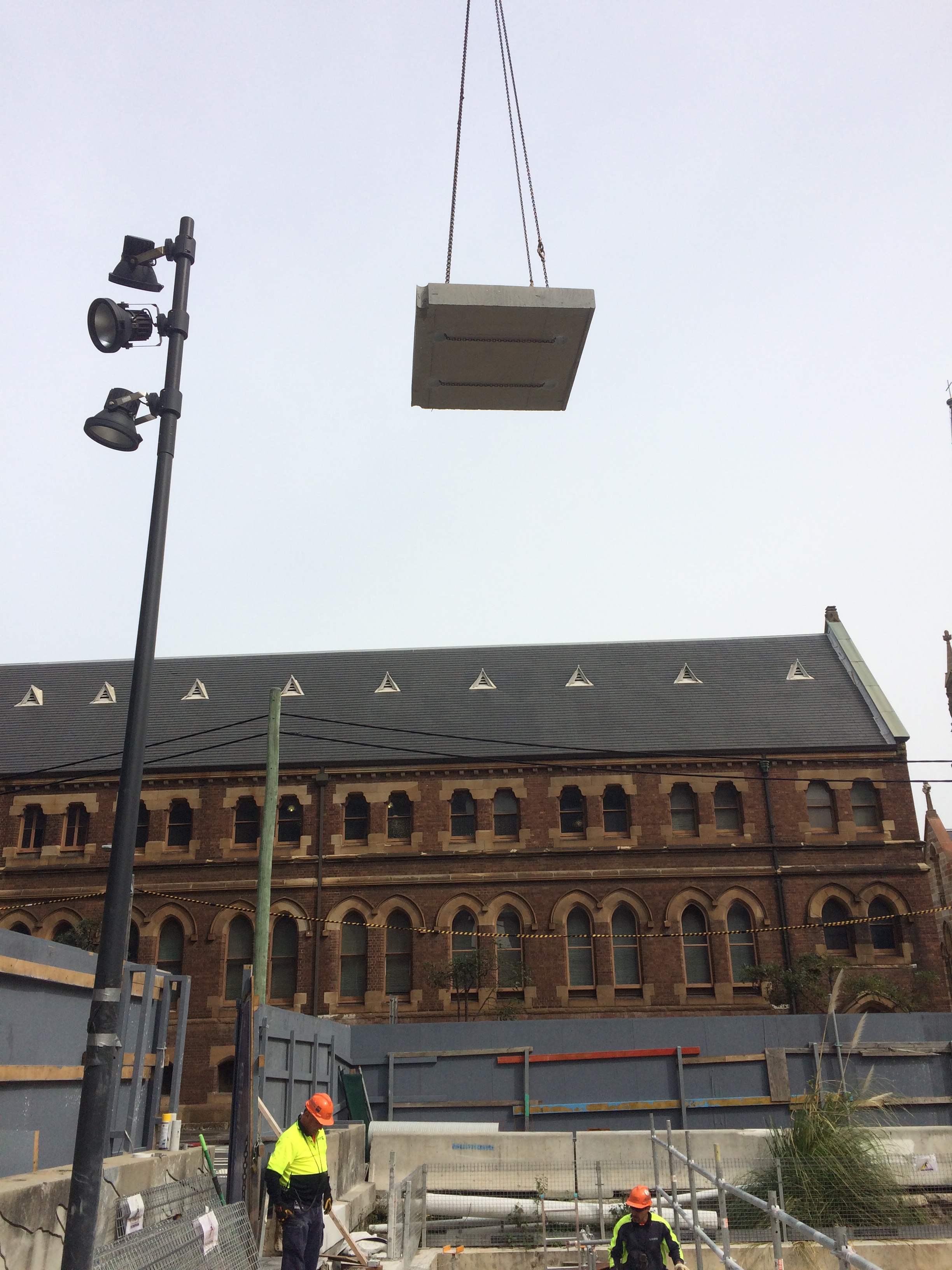
Step 6: The sections were then slung and lifted out for removal from site.
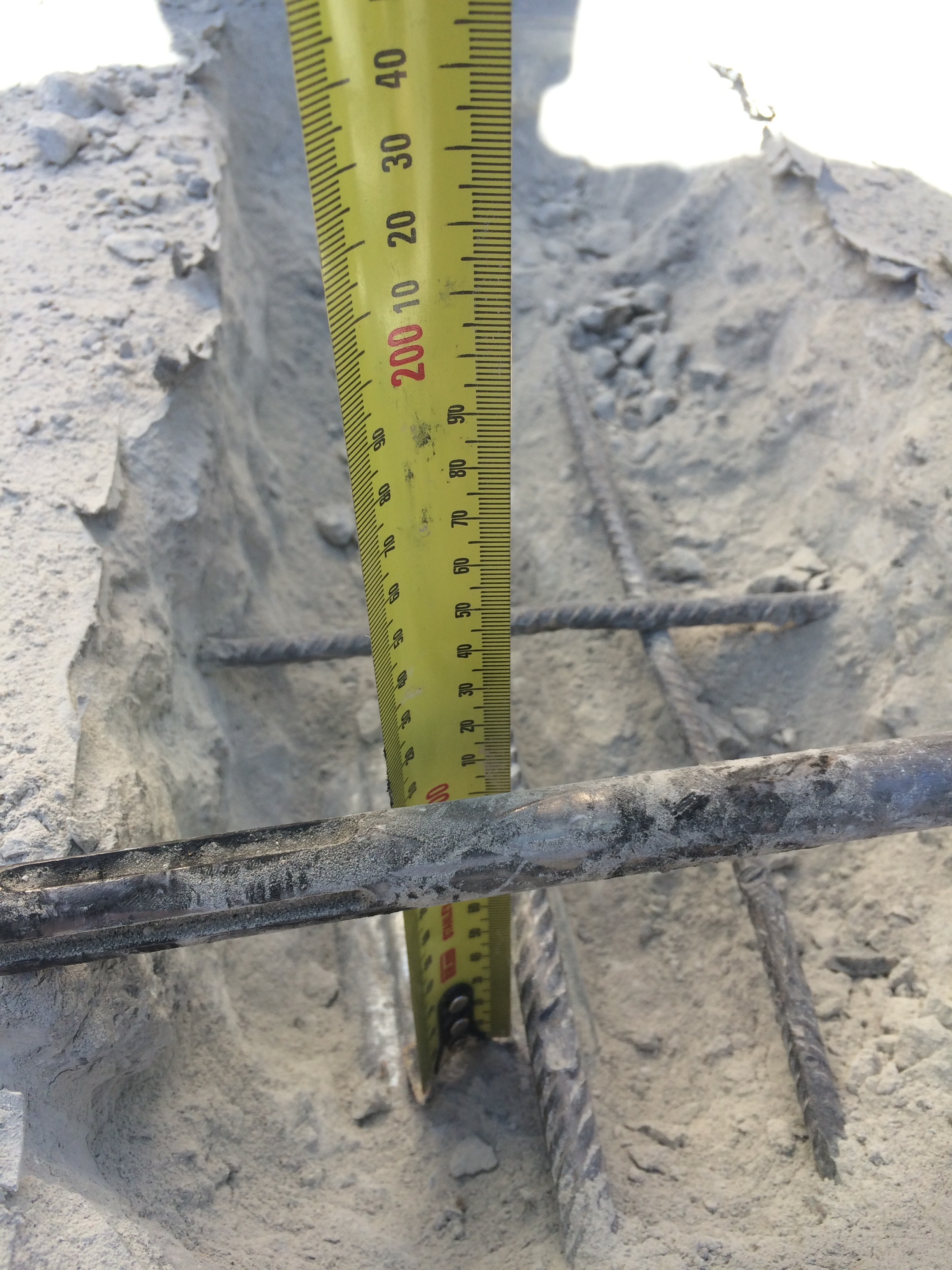
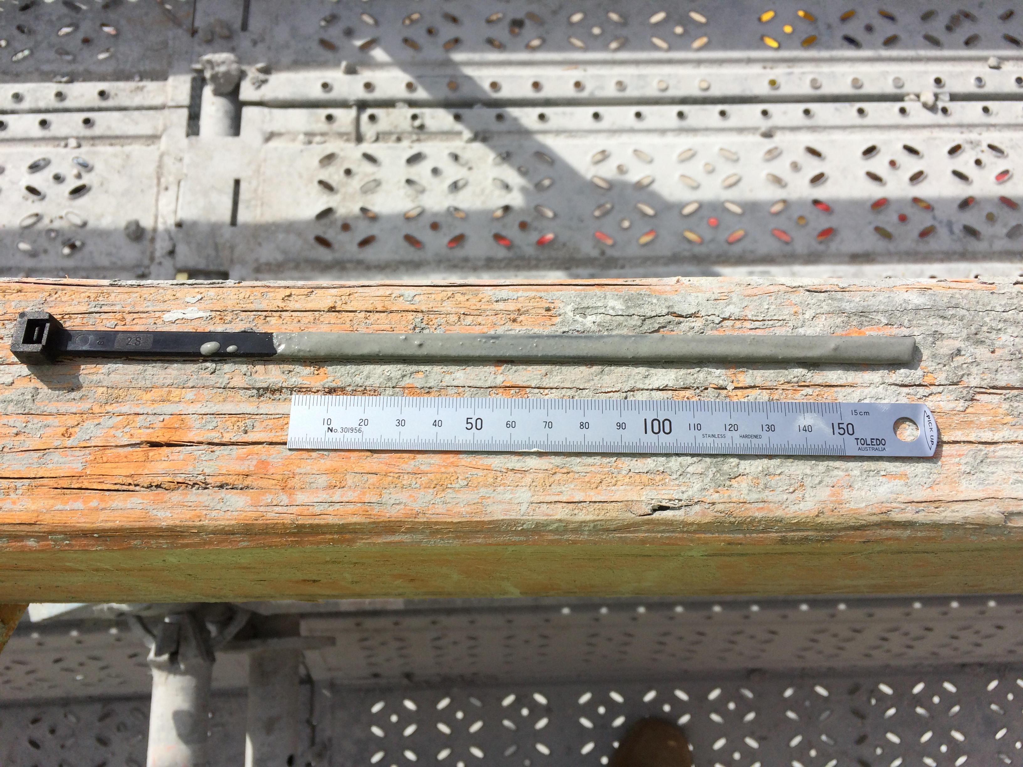
The final step involves treating the newly exposed PT tendons to prevent corrosion. On inspection we noticed that the PT tendons had slipped at 2 of the 12 epoxy plugs, one by 70mm and the other by 180mm. Initial analysis indicates that the slip is acceptable but an investigation is ongoing to work out why the slip occurred. In my opinion, it is worth noting that these two locations lacked grout around the tendons during the grout inspection. More is therefore being asked of the these epoxy plugs. It is also worth noting that the epoxy didn’t appear to be completely cured. In my opinion, these two factors are to blame for the slip, but hindsight is a wonderful thing and time is money apparently…
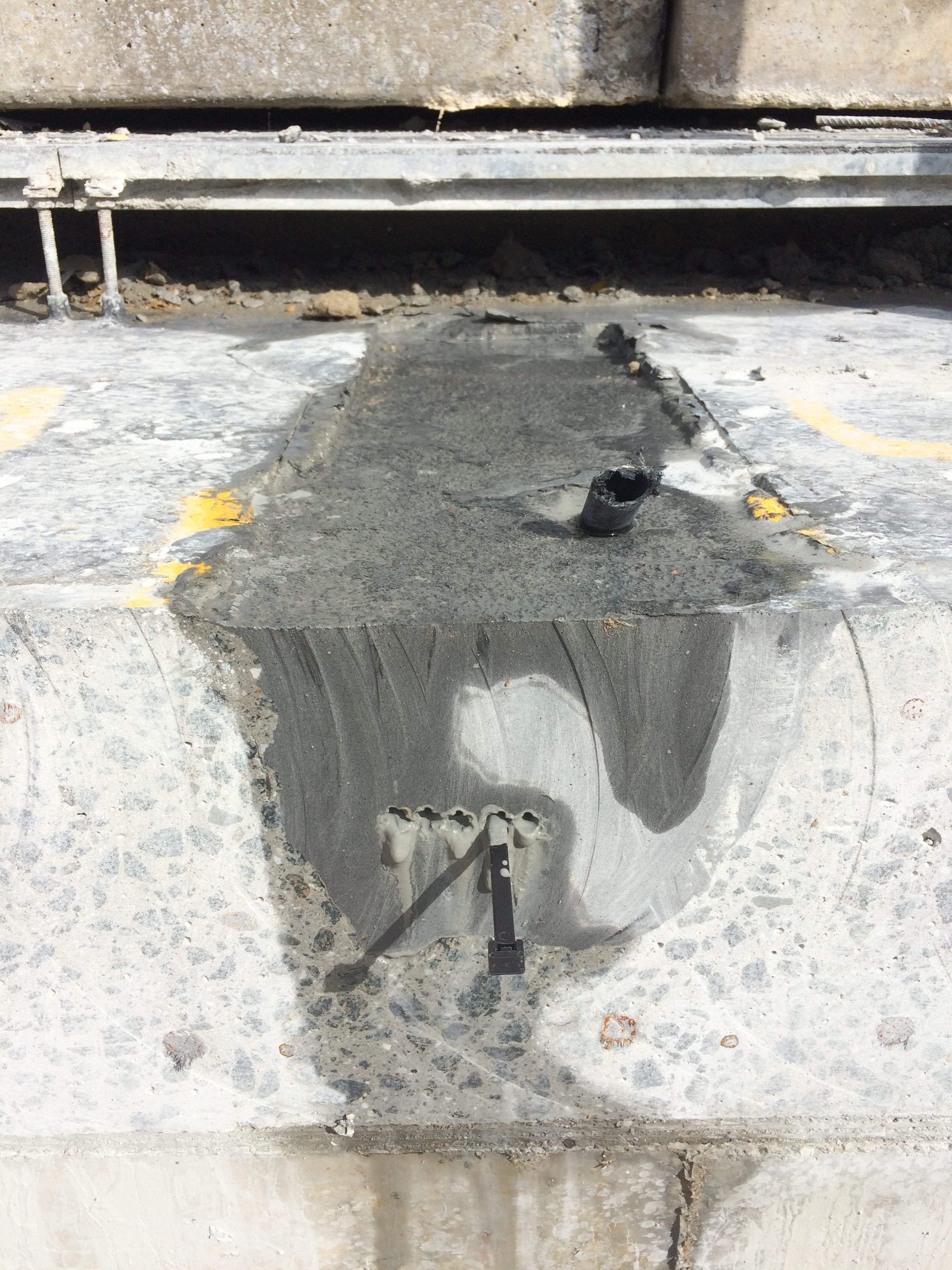
The image below shows the exposed PT tendon at the face of the cut. NB: no slip!
The image below shows slippage of the PT tendon at the face of the cut. NB: my high-tech cable tie measuring device!
More to follow…

Nice work mate. Good use of photos to explain the process.
By the sounds of it the slab wasnt supposed to be in your site boundary, as such who is carrying the cost of these adaptions? Having worked with your company in the UK I assume their normal approach of ‘find someone else to blame/pay’ applies and the contracts team is trying to land the bill on a neighbouring developers desk?
Thomas – your assumption would normally be correct however Multiplex have footed the bill for this one. They knew well in advance that the works had to be done so they accounted for it in their contract. This was an easier exercise than it would normally be as both building, old and new, belong to the same Client.
Thanks for that Andy. I don’t understand why the two red rectangles indicating reformed anchors exists on the left hand side of the rectangle to be removed. It looks as if the dead end anchor is to have a new anchorage formed adjacent and then the whole thing is cut out anyway? I am also intrigued by the method of forming a new anchorage by simply casting resin around the tendon – this implies the resin is expected to achieve a very high bond stress along the 500mm contact length. What was the original pre-stress force in these tendons?