Archive
Factory Acceptance Testing
Like Stu I have recently been involved in Factory Acceptance Testing (FAT) testing but rather than spending a day on a dusty farm, I attended one at the Carrier Test Facility in Lyon, France.
The FAT visit involved witnessing the testing a variable chiller unit. It was a very useful visit as it meant revisiting the refrigeration cycle and learning more about how chillers are constructed. It also included a nice hotel and slap up meal fully paid for by the Client! Here is a picture of the Chiller being tested:

The Chiller is a 1713kW single stage chiller that uses R134A refridgerent and has a Coefficient of Performance (COP) of 4.56. As you can see from the picture, it is in fact two identical chillers bolted together and these two work in parallel and not as a two stage refrigerator. This type of chiller gives better performance at low loads as only one side will be ran. In the picture, the grey cylinders are the condensers and are basically large tube heat exchangers. The condensate is circulated through a closed loop system (45degC flow and 35degC return) that sees it either sent to the cooling towers, heating system or to the boreholes (this system is fully controlled by the building management system being designed by Honeywell). When running at full load, the system provides 2.08kW of heating. The large items on the top are the compressors and the large black insulated cylinders at the back are the evaporators and supply chilled water at 9degC flow using a 14degC return.
Of particular interest was the economiser which I admit struggling to understand fully in Phase One. So here is a picture of an economiser:
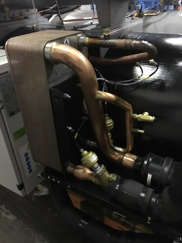
As I am sure, all of the E&Ms will remember that the economiser is used to create Sub-Cooling in order to improve COP. It works by diverting some of refrigerant leaving the condenser and then throttling it to the reduce the temperature. This colder flow of refrigerant is then used to sub-cool the main flow using a Plate Heat Exchanger (PHX).
To understand this system, I used a free to download programme called CoolPack. This program allows you to easily plot P-V and T-S diagram and conduct refrigeration calculations. I recommend this program to all E&Ms.
As part of the testing schedule, the chiller was ran and full, 75%, 50% and 25% load. Each time, the chiller was left for 30-45 mins to allow it to stabilise to a predetermined tolerance. Then the system was ran for a further 30mins and the temperatures and pressures were measured and plotted as shown below:
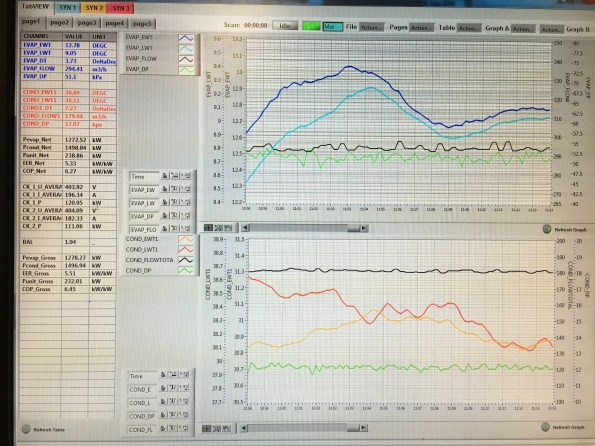
For each test to be signed off as acceptable by us, the chilled water supply and return and condensate supply and return had to be within a tolerance of the design temperatures. Also we checked the power consumption of the system, the heating and cooling outputs and COP for compliance. The Chiller passed all of these tests.
The final part of our testing schedule was to test fault conditions. To do this we increased the system pressure, simulated a loss of power and shut off the cooler pump to simulate a lack of water flow in three separate tests. For each of these tests we reviewed the chillers response such as instantly stopping, allowing the pressure to equalise across the compressor and the messages displayed on the Human Machine interface (HMI). The Chiller reacted correctly in all of the tests but during the high pressure test, one side shut down correctly and displayed the high pressure fault code but the other side shut down but displayed an electrical fault code. So we asked for the test to be ran again but for the faulty side to be ran on its own and this time it displayed the correct fault code after tripping. We also provide carrier with some requests as to how to better display messages and the visual layout of the SCADA system on the HMI.
This proved to be an excellent trip and opportunity to experience FAT testing. It also turned into a very useful refrigeration revision session!
I am hoping to do my next FAT trip to Austria next month and so look forward to a similar blog…….
Any ideas for removing props when stressed?
I am currently trying to build my way out of the 22 m hole I have dug for myself in South Brisbane. Progress has recently accellerated now that the excavation is over. In the last 3 weeks the structure has completed Basement levels 6, 5 and 4. we are currently at Basement level 3 and in the next week we will be at the same level as the props (Basement level 2), which presents some challenges. The props are significant pieces of engineering and consist of 900, 752 and 508 mm Circular Hollow Sections in each corner.
In order to keep the job moving we will have to remove two of the props that clash with the permanent structure (highlighted) and build over the remainder. This flies in the face of conventional wisdom but, lets focus on the problem at hand. The removal of these props is potentially very hazardous, since they were installed the wall has deflected inwards by up to 26 mm and as consequence the props could potentially be under 2-3 MN of compression.

Aerial photo taken of site (this was taken 3 weeks ago when we were on Basement 6)
Having just received my sub-contractors method statement (similar to how a lumberjack would cut down a tree). I concluded that they will kill someone so I have consulted the ‘hole diggers bible’ (CIRIA 517). Unfortunately, the struts are welded in to the walers so it removes a lot of potential options. I believe the only method left to follow is to cut progressively larger holes in the CHS while supporting them from either the deck or the tower crane.
Given that the deck will just have been poured and would require propping all of the way down to Basement level 6, I am reluctant to recommend this option. The sole use of the tower crane is equally unpalletable but, if it was conducted at a time when the majority of the site was empty it could work. I am open to any better ideas though.

Access. The props will block access around the site, so I have had to ask our scaffolders to build an access way on top of the walers. Unfortunately ladder access is frowned upon, so I have found some safety stairs that will be able get from the working deck to the temporary scaffold access. The safety stairs will be used in areas marked in yellow (above) that cannot be accessed by existing the existing stairs. We tested this on site today by placing them against the existing scaffold stairs.
Things are about to get very messy – I think its time to go on leave.
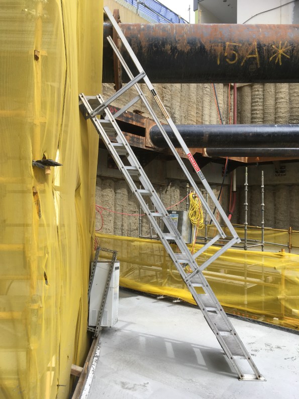
They are getting closer! -Photo taken from Basement level 3 of safety stairs against , props and walers in background (note we have built over the ground anchors now).
