Archive
Who needs a second runway anyway..!
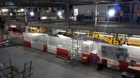
Well actually, Gatwick desperately does to facilitate its passenger throughput expansion plans. But realistically it will just be a matter of time before another is built here anyway. In any case, I thought an update from a rather subdued Gatwick was in order. The first major project of the baggage Programme is within a couple of months of completion. With no requirement for foundation or ground works and using a steel frame structure and pre-fabricated sections of baggage conveyor systems, the visual transformation on the new makeup positions site was rapid (see title picture).
The bulk of the remaining works includes the controls and electrical installations, as well as general road layouts, markings and safety barriers. I’ve picked out two hiccups that others will be able to identify across other sites.
Firstly, designing in a 3D model with inadequate detail. In Revitt, the walkway below had sufficient width (750mm) to serve as an emergency escape route. In reality, the motors from the conveyor systems (which had not been modeled in sufficient detail) encroached into the walkway. The outcome is that the walkway below needs new steel work in order to widen it by approximately 200mm. Whilst the amended steel work isn’t part of my works package, the electrical and controls containment and cabling that will run along its perimeter is, thus will incur minor delay.

Secondly, excessive lighting glare. The proposed flood light style system for illuminating the area where operators make up baggage containers has now gone up. Not considered as an issue during design due to the requirement to meet Gatwick standard requirements for illumination and glare, now that it is in situ, the glare from the lights may well cause a problem to the comfort of the baggage handlers. To try to head this off prior to hand over, I intend to firstly, ensure the contractor proves adherence to the required glare standards and secondly, bring the stakeholders together prior to completion and confirm acceptability, and if not, a suitable improvement.
Whilst the project is due to finish just about on time, the most significant delays to the project were due to Gatwick Airport process issues (such as the change control systems) rather than any technical or unforeseen engineering issues.
This will be one of my biggest takeaways from working in a live operating environment – factoring in time for the project team (most of whom are new to Gatwick) and contractors’ project teams to understand and meet the clearance process requirements of the numerous stakeholders during any engineering works. This could be for the simplest of electrical isolations, to fire systems deactivations, to emergency light testing.
Outside of baggage projects, I’ll be playing the role of dummy passenger supporting one if the other big programmes being delivered here – the Airline Moves project. This project consolidates all EasyJet flights in the North Terminal as from end of January, and moves all BA flights to South Terminal (plus a load more moving parts). My role will be to prove the route and identify faults from check in to boarding prior to the project going live.
Trouble at Mill No 2
As you can tell by the title it has been yet another fun week at Queensland’s premier building site – Quality and safety are our number 1 priority. It all started so well. We were are back at ground level, the sun was shining (30C) and all was right with the world.
Then Frankipile (Piling Sub-contractor) showed up to trim back some of the out of tolerance secant piles that are protuding into the basement and things started to unravel. Franki’s plan was to use a sub-contractor to trim back the piles. Unfortunately this needed to happen so that we could build the stairs in the basement. The original plan was to use hand tools to cut the piles back but we were concerned about noise and dust. So Frankipile brought in a hydro-demo subbie to keep the dust down. Now in the initial Sub-Sub-contractors Recce I asked 4 things:
- Would they put up screens to stop the flying bits of blasted concrete going everywhere and clean up afterwards?
- We are a Tier 1 site and therefore a Unon site so are you Enterprise Business Agreement (EBA) Compliant?
- How much water are you going to produce?
- Can they submit Safe Work Method Statements (SWMS)
The SWMS are a kind of method statement and and risk assessment in one. When I and the safety manager checked them they were amongst the best we had seen, so we thought we were dealing with a professional outfit. However…
- What actually happened. None of the guys were in the CFMEU union and the company was not EBA compliant so the Union delegate refused to let them on site until they were being paid at Tier 1 rates. This took half a day to organise.
- Quite simply you pay peanuts and you get monkeys. After being cock-a-hoop that their wages had double they tried to walk on site without PPE. They hadn’t brought any PPE with them, any signage or crucially barriers.
- Quite simply I have seen JDAMs make less mess than these idiots and the noise was absolutely deafening (think jet engine). I managed to confine them to the lower basements but the Union delegate was doing back flips.
- Water. I had asked that they bring sediment sock with them to filter the water before it went down the spoon drains and into the drainage tanks but there was so much water and so much debris in the drains that they soon flooded the slabs. Which soon ended up going through every penetration we had in the floor. Now Ozzies don’t do rain or water. If they get wet they go home on full pay so this became a serious problem I had to solve.
- Supervision. Frankipile exercised no control over their sub-contractor so it became my problem. I gave their Engineer a good gripping and told him to get his backside down to site with a crew ASAP to start cleaning up the mess. I had to get the electrician out to shut down several electrical boards and have spent the last 3 days with cleaners. Smashed concerete was everywhere and I ended up filling 8 skip loads with the rubble from only 10 piles! I have had to fight tooth and nail to get these skips exchanged as in military terms I am off the main effort.
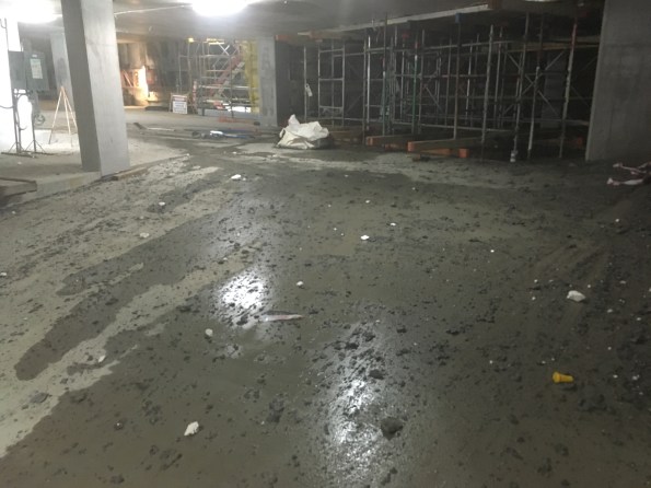
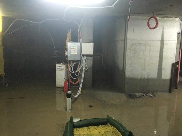
Basment 6 – Electricity and Water a winning combination.
On Thursday the Union took the opportunity to do a snap inspection during clean-up and came mob handed (5 Union officials) to shut down the job. The irony is they told the guys who were cleaning up to stop because it needed cleaning up. The mess wasn’t the only thing wrong with the site but, it certainly didn’t help. These union inspection always have their own agenda other than safety, which goes some way to explains why 5 delegates turned up. I don’t know the full details but the Saturday shift has been cancelled (every cloud) – and my clean up was on the main effort.
So what have I learned:
- After spending 3 days clearing rubble and water, I no longer trust anyone.
- I should have thrown them off site in the morning.
- I will always check companies are EBA compliant before they arrive.
- I will insist that the sub-contractor provide a supervisor to manage their subbies – work will not start without one.
- I will stop work if it does not adhere to the SWMS.
- All sub-contractors are idiots unless verified otherwise.
- Clear everything with my comrade delegate (commissar).
Site Update, many activities
No major problems on site but I thought that a more general site update might be due (especially in light of a potential placement for next year).
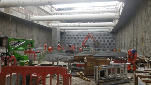
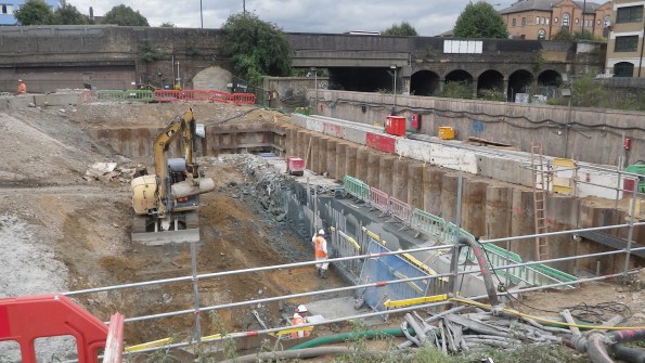
Recently in the last few weeks the activity has steadily increased as the TBM parts have been delivered on site and the SCL (spray concrete lining) team are setting up. Many robotic tracked vehicles driving around. This has all come as the primary works in the Crossover box come to an end. Construction of the box is as far as it will go until the TBMs have finished tunnelling. So there is a oncoming shift in focus of the main civils team from the Crossover Box to the Station Box. The work force on site has also ballooned 3 times what it has been for the last year.
Crossover Box
Excavation. The excavation has now been completed. All the props strain gauges are showing that they are behaving as they are expected and shape arrays in the d-walls are showing expected deflection. Now that the excavation has finished the monitoring will be reduced and shape arrays and relocated to the Station Box.
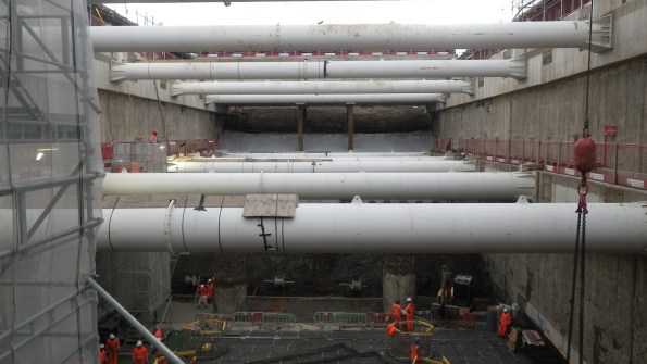
Crossover Box from B-02 level
Crossover Box from B-04 level
Soil Nailing. The last of the excavation has been possible due to the soil nailing. Over the last week BAM Nuttal has been sub contracted to install six rows of soil nails to stabilise the clay at a 70° slope. This required 24hr working to excavate 1.2m high benches into the clay at night, so that nailing could take place during the day. This is a semi-temporary condition, for up to a year. The London Clay was holding well, but for how long… no one knows squared.
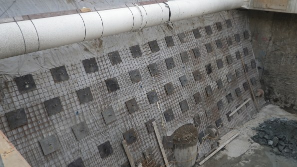
6 rows of soil nails
Base Slab. A third of the base slab (pour 1 & 2) 1.5m deep, has been completed with the middle third pour (pours 3 and 4) planned for Thursday. This has gone largely without incident… surprisingly.
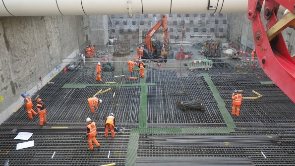
Steel fixing base slab pour 3 and 4.
Headwalls. The stage 1 headwalls are being cast today. They are essentially columns cast against the d-wall. These increase the stiffness of the box and provide additional load capacity to allow two 6m diameter holes to be removed via stitch drilling. The headwalls are 6.7m high and are being poured through guillotines in the formwork under pressure. This has required a lot of planning, much more than usual. It’s the first time such a high pour has been done for most on site, its going smoothly so far.

Temporary Bridge. In addition DAM structures are about to finish the erecting of a steel bridge over part of the primary structure. This will provide access across the site once the excavation has started on the station box side. The steel has just been finished. The RC deck is not being constructed (you can see some of the falsework in place at the far side.
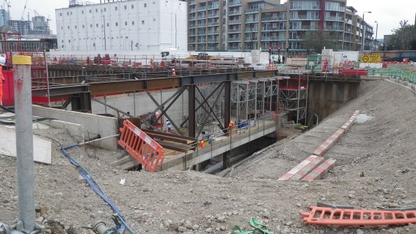
Steel Bridge complete – RC deck under construction
Station Box
Piling and D-walling. Rotary bored piles have 5 weeks left on site which will provide quite a bit of relief as the ancillaries (casings, augers etc) for 4 sizes of piles and the polymer plant are de-mobilised.
D-wall panels are currently 39% complete. This is a delay of 4 weeks so as to reduce the impact to the FLO works, my time has been largely taken up negotiating a phased handover ahead of the completion. As expected this is highly contentious. Lots of commercial discussions but we now have a solution that should keep FLO on their programme to built target and CSL with enough room to actually complete the piles.
Capping Beam Construction. Lastly, following the handover of the first 4 gridlines (24m long) FLO have started to break down the d-walls and have started the construction of the capping beam.
First section of Station Box Capping Beam.
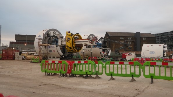
Semi assembled TBMs
Are all QS mental?
This isn’t directly aimed at Greg Tripp, but maybe he can help me understand why I find myself wanting to dispose of all QS at the bottom of a rotary bored concrete pile!
During piling activities a byproduct of the process is pile arisings, or spoil. In our case this is sandstone (more like builder’s sand). This needs to be removed from site and we have a sub-contractor who is paid to do this.
My first assumption was that when a tipper lorry collects spoil from site and then leaves through the gate, the ticket they leave will be used to quantify how much spoil has been removed. This will then be used to complete the valuation each month for the sub-contractor removing the spoil.
I have been asked by the QS for details on the volumes of the piles as this is actually the quantity they use to complete valuations (not what actually leaves site). I have a number of issues with this:
- What bulking factor is being used – 1m^3 of bank is not 1m^3 of loose.
- Not all material from piling is being taken off site. A large amount is used on site to improve underfoot conditions and the working areas for sub-contractors.
- Other sub-contractors also use the spoil to back-fill in their own areas (where the SES allows)
So I believe the SC is getting paid to remove spoil that is staying on site. When I discussed these issues with the junior QS, he asked me to quantify how much is being left on site – I had a look up my sleeve but was still found wanting on this figure – it’s like trying to quantify the amount of icing sugar in my cocaine.
I see the issues with paying for tickets:
- The tipper lorry may not be full
- The spoil may have come from another location or task
- Tickets get lost
But these issues can be easily controlled; the gate man can confirm the lorry is full (or 1/2 etc). Spoil on site is separated in the tasks it has come from in case of localised contamination. The gate man also keeps a register of vehicles entering and leaving site which will back up lost tickets.
I am yet to consult the QS Pocket Book, but this is my next step. I have so far given in to the QS and delivered the information they have requested.
I have another QS rant where they have specifically gone for a day-works contract over lump sum, because it was initially cheaper – again I argued against this but the QS insisted she wanted all of the risk and none of the security (facetious)…
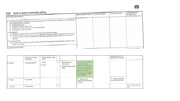
From the Standard Methods of Measurements 7th Edition, the item highlighted in green states:
The volume of disposal of surplus excavated materials is calculated from the nominal corss-sectional size of piles and their lengths measured in accordance with 1 & 2.1.2. The volume of enlarged bases is added to this calculation.
Everyday’s a school day!
Removal of props
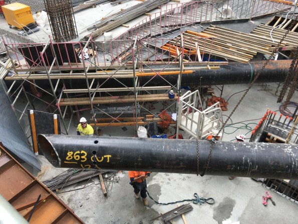
A 700 mm CHS being removed. Note the remaining props being built over.
A few weeks ago I promised to keep you updated on how the removal of the props was going. You can see by the photo the infill around the stairs has been filled and that I followed the advice of cutting 100 mm holes in the props to de-stress them. The removal of the props occurred pretty smoothly.
The only problem I encountered was that my boss had misinterpreted a consultants advice which caused me to check the capacity of the steel left and the concrete slab. After determining that it was ok, and after the said consultant went dark and refused to answer his calls we proceeded with the demolition as planned.
Anyway all went well but a tense moment and that was a floor ago.
What the site now looks like now – We are back at ground level and currently building the transfer slab with PT concrete.

However – I am still dealing with what we have left behind. More to follow…
![IMG_5145[1].JPG](https://pewpetblog.com/wp-content/uploads/2016/10/img_51451.jpg?w=595)
In foreground a 900 mm CHS and Double 1200 WB left behind.
REACTIVE NOT PROACTIVE
A series of events has unfolded over the past few weeks which has reinforced my utter contempt for the reactionary nature of site works; a common theme on Phase 2 WhatsApp chat. BPS Phase 3 basement is a 13m excavation, 16m in some locations. Along the southern boundary (adjacent to the Northern Line Extension site) the embedded retaining walls used are sheet piles. The contractor is unable to use vibratory hammer techniques to drive the sheet piles due to the proximity of the largest brick clad structure in Europe (Battersea Power Station). The 23m long sheet piles are thus driven using a silent press. The geological succession is typical London stratum. Made ground (crap), Terrace Gravels (medium dense sandy gravels – very porous), London Clay (very stiff – not very permeable) and Thanet Sands (very dense silty sand – porous). Due to the required toe depth, in the London Clay, pre-augering and water jetting techniques must be used. For the civils students the problem bears remarkable similarities to Ex COFFER.
The following photos below provide an indication of the works.
 Pre-augering Works
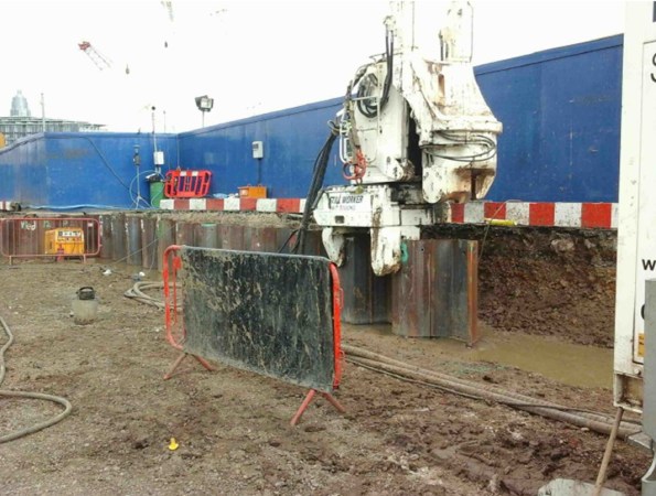 Sheet Piling Works using the silent press
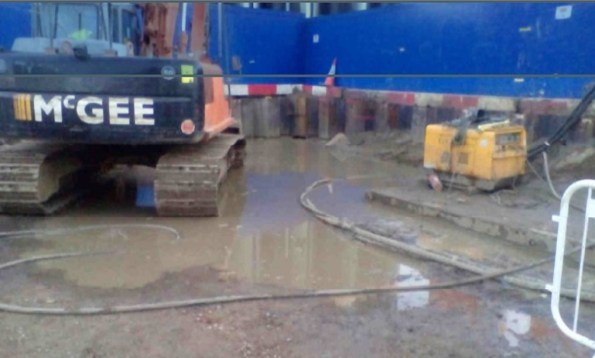 The aftermath of Water Jetting
The Inevitable Collapse
The previous photos show the steep batter adjacent to NLE site and there is a risk of undermining the adjacent site. However, sheet piling works continued whilst the contractual wrangling from the piling contractor and ground worker simmered in the background. Both parties claimed the other was responsible for fixing the problem. The inevitable happened and the batter gave way, undermining the NLE site, next to Polymer tanks. This incident has added further friction and incurred additional expense as BPS Phase 3 must repair the damage to NLE site. All in all a foreseeable incident that could have been avoided if stakeholders had looked beyond their blinkered “it’s not my responsibility” approach.
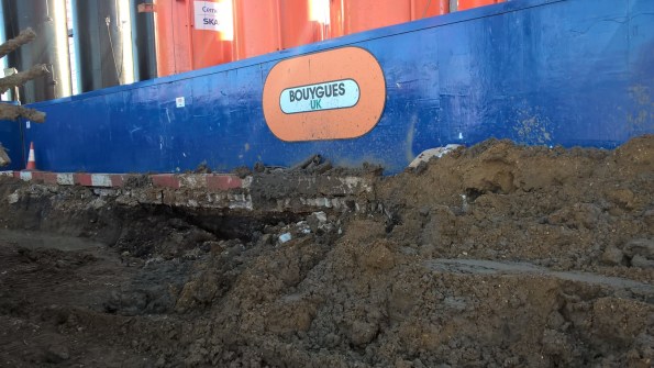 Batter Collapse
My original comment: “utter contempt for the reactionary nature of site works” may seem a little unfair given the circumstances detailed above. Never-the-less I think my comment is well founded given the final photo taken AFTER the batter collapse which was the piling contractor’s response to dealing with one of the contributing factors (disposing of the excess water)…
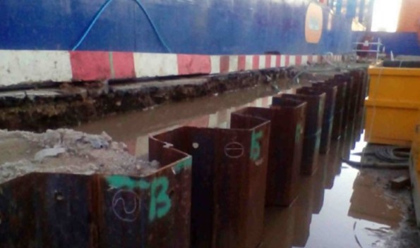 The contractor’s solution to the excess water – discharging the water behind the sheet piles further washing away any batter! However in their defence apparently contractually: “It’s still not their responsibility“
Bloody Boring
A while ago I was appointed the lead for the construction of a £1.2m borehole field for a Ground Source Heat Pump (GSHP) System. This has been a challenging task as it has meant working closely with an Austrian Sub-Contractor and numerous Sub-Sub-Contractors to design the field.
The borehole array design has taken 3 months to develop and finally sign off for construction. The final design is for an array consisting of two fields totalling 170x 200m deep boreholes arranged at 6.5m spacings. The design also includes six monitoring boreholes that will allow us to measure any heat flow between our borehole field and the two neighbouring borehole fields as it is a real risk that ours could steal heat from our neighbours and so result in financial penalties.
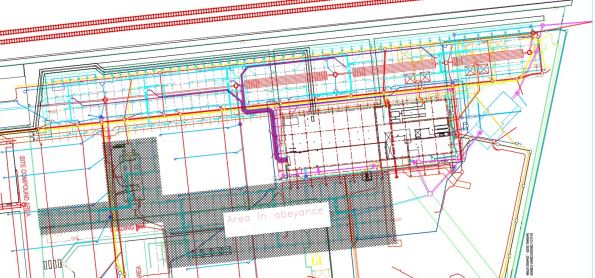
The normal recommended spacing between boreholes is 7m due to boreholes not being straight and to ensure suitable heat storage. The sub-contractor calculated that a spacing of 6.5m was acceptable in terms of heat flux density and that the boreholes would not collide at 200m. However using this figure gives very little room for error and so once placed in the borehole array lattice, the boreholes are fixed as any movement would reduce the separation below 6.5m and risk the boreholes colliding at depth. The design has proven to be a challenge and so several weeks ago I decided to split it into two smaller designs so at least a section could be approved for construction without delaying the start on site date. This has led to a two phase construction programme with the design for the second phase currently in abeyance. Here is a drawing of the finished design with the myriad of constructed and planned underground services:
The main issues for this prolonged design period has been:
- Buried Services. Generally borehole fields are constructed on virgin sites and so services aren’t an issue but due to project delays and a last minute change of sub-contractor, our borehole field is being built around existing services including drainage, attenuation tanks and HV/LV cables. Deconflicting the boreholes and services has been a real nightmare and taken up a surprising amount of my time. If I were to be involved in constructing a borehole field again I would push for the array to be constructed as early as possible and before the majority of underground services.
- Future Landscaping. We have also had to change the array design to take into account the future landscaping so that the boreholes and connecting pipework will not be damaged by tree roots or will not sit in ponds.
- Principal Designer. Since we are not the Principal Designers, all designs have to be signed off or agreed with the designers, BDP. BDP very rarely visit site and do not have a great understanding of the borehole design nor the work involved in its creation. This has resulted in designs being rejected with BDP requesting investigations to be conducted despite this work already been conducted by my team during the design development.
- Technical Submissions. The Sub-Contractor submitted datasheets for my approval and approval from BDP. Unfortunately further investigation showed that the pipes that run through the borehole were not rated to 20bar (the pressure of water at the bottom of the pipe) and the Thermal Grout (Bentonite and Silica Sand) had a thermal conductivity of 1.7W/Km2 whereas the design specified a conductivity of 1.8W/km2 and the thermal simulation was based on this figure. After rejecting the proposed materials, the sub-contractor and their supply chain conducted a number of pressure tests on the pipework and changed the grout mixing ratio.
- Contractual issues. There has been a disagreement about who is responsible for providing power and water and this has forced me to dig into the contract to resolve the conflict. the result was that I recommended that the Client should instruct the Sub-Contractor to supply a generator but that the costs should be borne by the Client due to the Client not performing his obligations under the existing contract. The Client agreed and the instruction was issued through change control. Also we stipulated that the lifting plan for some of the plant machinery had to be written by an A61 qualified Lifting AP as this is Skanska Policy. This meant that the Sub-Contractor had to pay a third-party AP to rewrite and sign the Lifting plan and the ensuing arguments have damaged our relationship with the subbie – something I am keen to resolve. So after scouring the contracts I was able to prove that this requirement was not specified as part of the tender enquiry but was first mentioned after the contract was signed and therefore can only be enforced through change control and at cost to the Client. I am awaiting approval from the Client for this change request.
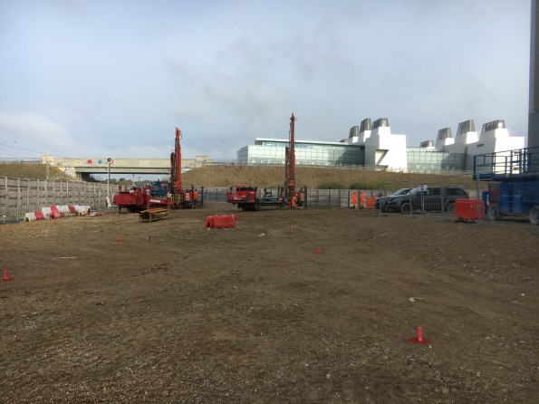
Anyway, after months of redesign and compiling the mountain of paper work and permits required to get a sub-contractor on site, the sub-contractor broke ground today which is a milestone for our Project.

The Sub-Contractor has deployed two rigs to site and will construct and test two boreholes per day. We are now awaiting the arrival of the mud-cleaning equipment and grout materials before work starts in earnest next week. As well as checking and supervising the daily works, I have just initiated the design of the second borehole field and the inter-connecting horizontal pipework for the first field which is due to be constructed in four weeks.
This experience has resulted in a few lessons learnt:
- Borehole fields should be built as early as possible in a project as services are easier to move than boreholes which have a fixed separation.
- Under Management-Only contracts, the Principal Designer should be included in design meetings throughout the design process to give them greater situational awareness and to streamline the approval process. They may require some ‘motivation’ to get them to attend site meetings!
- Never assume that the materials selected by the sub-contractor are fit for purpose or suitable for the design so interrogate them.
- When writing a contract be explicit as to who is responsible for providing on-site services and ensure the Sub-Contractor acknowledges these requirements during the Pre-Start meeting. Where practical, in the scope document/contract, instruct the sub-contractor to include for the provision of their own power and water and include it as a cost item in the pricing document (BoQ/Volume 3). Then if the Main-Contractor/Client can provide mains water and power, omit this cost as a saving. If this is not possible then ensure that the cost of providing a generator (in case site power in not available) is listed on the risk register so it is still included in the cost plan.
In a few weeks I will blog about how the boreholes are constructed and tested as an interest piece and hopefully this will coincide with the Phase 1 E&Ms learning about GSHPs.
Yesterday we awarded a £1.5m package which I developed from conception and led through tendering and wrote the contract for so I will also blog about two-stage tendering and sealed-bid tenders and my experiences of them. I am trying to get the newly appointed sub-contractor on site on Monday 31 Oct 16 to start the fit out of a 132m long 4m wide services tunnel but this is tight and does not leave a lot of time for pre-start events and approving RAMS and Lifting Plans. So a busy week ahead…..
Concrete Chaos
A few weeks ago we completed the first of our substantial concrete pour operations in order to construct the main tower core pile cap in our basement. This is a big block of concrete. The pile cap is roughly 18m wide, 36m long and 3.5m metres deep giving a total C32/C40 concrete volume, with quite a few lift pits thrown in for good measure, of 2830.5m³. We are constructing it in four roughly equal sections. During the first of these pours we emplaced 610m³ of concrete in one go. The pile cap will eventually carry roughly half of the 40 storey towers structural load so getting this right in terms of quality is important. This task was also on the critical path so ensuring it went in error free and on programme was a major concern. As the blog title implies, all did not go to plan.
Whilst my ability to walk over re-bar mats without looking like an amateur construction worker is improving rapidly, even I felt reasonably uncomfortable being stood on top of the cage suspended 3m in the air with clear sight to ground. The top mat re-bar inspection is probably the most unsafe I have felt at any point on this project. The potential to fall through a hole in the mat or beak an ankle/leg was alarming, as such work was stopped on multiple occasions to address H&S concerns. Thereafter I took to doing re-bar checks from Ground level looking up. Despite its considerable size the re-bar cage is a surprisingly simple design made up, in general, of 32mm dia bars at 200mm spacing’s. We have 4 layers in the top and 4 layers in the bottom.

Unlike most concrete pours the interesting thing about our methodology is that once the formwork is stripped away it’s conveniently easy to inspect a complete face of the pile cap throughout its whole depth. This makes post pour quality assurance checks considerably easier for the main contractor whilst also making it more difficult for the sub – contractor to hide any poor work underground.

The above picture shows the top 1.5m metre of our 3m deep concrete pile cap once the formwork had been removed. The structural engineers were initially quite concerned about the concrete quality. If you look closely you can see horizontal lines running in the concrete throughout its complete depth. Initial concerns were that the pour process had enabled horizontal cold joints to form between delivery loads of concrete. Had that been the case, then we were concerned we had produced a concrete block with weakened shear planes running through it. The question I tried to get answered was: why is this a problem? As I see it; If you simplify the pile cap in the permanent condition and consider it a large beam (the concrete block) carrying a large UDL (the tower) through numerous evenly distributed supports (the load bearing piles) then I think you would end up with a very simple FBD and BM/ SF diagram. With a few convenient assumptions and a quick check on google I think it would like something like the following
If indeed this pile cap behaves like a beam (And not a reinforced deep truss) then it sees greatest shear over the pile positions. Under the load of the completed building multiple horizontal cold joints caused by poor installation will undermine the capacity of the concrete pile cap, particularly in those positions. As it’s such a vital structural component stripping out this concrete and starting again was suggested by one overzealous member of the construction team. That was quickly put on hold because breaking out 610m³ of heavily reinforced concrete would be very unpleasant, not to mention crippling for our tight programme. As such an investigation was completed and after chipping away 30mm of concrete face the effect disappeared and with it the concern over the complete block. Had it continued we would have cored into the concrete block in a desperate search for any shred of evidence that would have prevented the need to strip it out.
Interestingly, even had we found weakened horizontal shear planes running through this mass of concrete, automatically stripping it out would have been a hasty reaction. When you look at it simply, all we need to do is install a solution that allows shear to be effectively transferred between the layers. Conceptually this could also be achieved by post fixing shear links into the pile cap by drilling and installing vertical reinforcement steel rods through the concrete. If we emplaced enough steel, focusing on the areas where the shear is known to be greatest, it is likely we could provide enough shear resistance to mitigate the long term risk. This would be difficult but considerably easier, quicker and cheaper than stripping it all out and starting again.
We are still unsure what caused this effect so consistently. In general concrete work seems reasonably poor quality across site. At the time I asked the concrete sub-contractor what lessons they had learnt and what measures they were putting into place to improve this process, they couldn’t give a particularly good answer; concerning when you consider our next pour was 850m³ of the stuff.
Attention blog administrators.
The blog memory if currently at 99.9% of its 3GB capacity, if we reach 100% there can be no more blogs………..
My slightly unorthodox Ph2/3
It’s nearly November and I guess most people are starting to get towards the end of their site phase and are looking forward to a bit of leave and then the design phase (hopefully one or two people are thinking about growing a moustache). Early on in my attachment I decided to try something a bit different and sought to combine both Phase 2 and Phase 3 into one Phase 2.5. There were a couple of key drivers for this:
- The project is due to complete in June 2017, so I would be able to see the services element of the project from design development, to installation and through to commissioning and handover.
- When I joined the project there was still a significant element of design development going on: everything from high level services coordination and clash prevention, to user workshops to refine whole room layouts and to finalise designs for key elements within the clinical spaces. This meant that there was initially very little on-site activity for services but it also gave me exposure to some of the design competencies very early on.
- The services manager on the project wholeheartedly embraced the concept of the attachment and was able to organise attachments with subcontractors and consultants in order for me to gain exposure to detailed design concepts, requirements and software.
- The possibility of an extended secondment to Multiplex’s head office to work within the New Projects Department for exposure to the commercial and contractual elements of tendering and resourcing multi-million dollar projects. This has recently been confirmed and will be timed to coincide with the production of my draft thesis.
So far everything has been running fairly to plan – below is a snapshot of these I think I will be come the end of my Ph2.5.
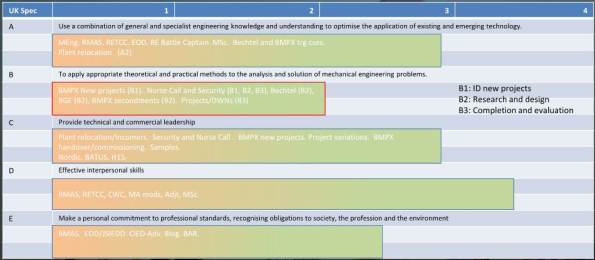
I have highlighted the B competencies in the chart as I believe that of the 5 areas, the design will be my weakest come Ph4 and I will be relying heavily on the experiences gained during my 18 months working in an Oil and Gas design office before joining the army, the design development work from the St George Hospital Project and the short secondments to subcontractors and consultants.
Despite possibly leaving me slightly exposed in the B competencies, I believe that the experience of seeing a project from start to finish will greatly out-weigh the lack of detailed design experience. And I guess if I am wrong then I will just have to come back to Oz and give it another go!
