Archive
Contract Incentive?
Apologies for another post in such a short period from my last one; I will try and keep it short. In the last month the tunnel vent project seems to have reached the ‘money grabbing’ stage that Gregg and Steve described in their phase 1 lectures … the budget has run out, instructions have dried up and the client (Crossrail) is looking over our shoulders.
In contrast to many projects for commercial clients the Tunnel Vent NEC 3 ‘cost plus’ agreement is geared to incentivise quality above programme, cost or anything else. Therefore, bizarrely, there are no programme-linked milestone payments or costs for over-runs; all that the contract allows for is the reduction of the contractor’s fee. This is illustrated in the graph below (the risk element covers insurance costs):
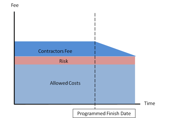
ATCjv cost profile showing tapering reduction in fee past end date
The main way the client is looking to claw back funds is to find disallowed costs… basically finding evidence that we are incompetent or cutting corners. As a result at the point of the project when the contractor (ATCjv) should be concentrating most on the installation phase we are instead trying our hardest to cover our tracks with EWNs and hide mistakes behind other contractors delays.
I’m not sure how many sites would finish on time if their incentive scheme was set up in this way? I look forward to see if the Elizabeth Line opens on time in summer 2018….
Load Testing with a Difference– 25 NOV 16
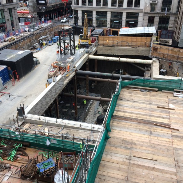
So Bridge 1 is complete. This is the temporary structure that cuts across our site and provides access to adjacent phases. Its construction will facilitate our basement excavation in due course. Broadly speaking it is a motorway over bridge. It spans 80m over 9 spans (the largest of which is 18m) has a 7.3m carriageway with a maintenance footpath on either side. It has been delivered on time, on schedule and possibly to budget… Probably not to budget as the client’s scope was so vague that the trade contractor has taken him to town with additional items. I have spent the last month or so compiling Site Instructions to complete the bridge in line with the client’s intent.

Bridge 1 Aerial View – An adjacent phase 40T artic can be seen on the bridge ready to be offloaded
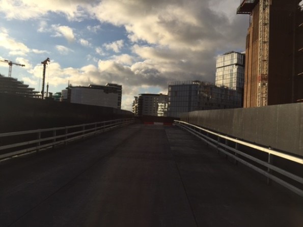
Bridge 1 – Deck View
Most recently, I have hosted a series of visits from various client representatives that have not just moved the goal posts but completely changed the sport… The design brief was cast in stone well over a year ago. The structure of the temporary bridge was to be designed as a private access road and therefore Highway regulations did not apply in their entirety. Clearly, the client and designer cherry picked areas (crash barrier rating and bridge loading for example).
From my perspective, the past month or so has been challenging, the client’s expectations are wholly unrealistic. My “favourite” client check was the load testing dry run conducted last week. Photos below:


Porsche Load Testing
The test to confirm the ground clearance for sports cars was successful as the Porsche did not ground out at any point. However, from my perspective, given that the gradient was dictated by the existing road profile at the entrance to the site and the final road level at the permanent HALO Bridge. How could the bridge deck profile have been altered had the sports car test failed? Answers on a self-addressed postcard please.
Sustainable development on site
Fellow PETs, rather then clog up the Watsapp I thought I would bring a query here…
Whilst writing AER 3 I have noticed that I have still some way to go to get ‘Ability’ within ICE attribute 7 – Sustainable Development and I was wondering what methods other sites have. On site at Southbank Place there are a few schemes that they have used to try and tick the sustainability box; they have employed operatives from the surrounding area, use sustainably sourced aggregate for the concrete (according to London Concrete anyway!), used precast elements in the design and not worked past 1800 so that there is limited noise pollution. To me, there does not appear to be a massive emphasis on being sustainable; it is just a box to be ticked. I went to Laing O’Rourke’s in house lecture (delivered by the project leader on site) on how they are improving sustainability across the business. The project leader managed to cram the hour long presentation into 10 minutes and left me with the feeling that sustainability was viewed more as a hindrance than anything else.
Has anyone had similar experiences? What sustainable development initiatives have you had on your site?
Having a cracking time – wish you were here!
There have been a lot of posts about concrete recently so I thought I would throw my hat into the ring with some issues I have been having with reinforced and post-tensioned concrete. The client was walking around site and went mad about some surface cracking that we are experiencing in the car park. This sent the PM into a flap and I was sent out to investigate. I took these photos of the area she was concerned with.
![IMG_5557[1].JPG](https://pewpetblog.com/wp-content/uploads/2016/11/img_55571.jpg?w=595)
Surface Cracking caused by rapid water loss.
![IMG_5554[1].JPG](https://pewpetblog.com/wp-content/uploads/2016/11/img_55541.jpg?w=8064)
A crack along the top of a ramp – not really a concern though.
However, while on my crack patrol I came across this crack- that hadn’t been spotted by the client or the PM. Now it is big enough to fit a credit card into so I was concerned. I immediately checked the propping and found it to be in good order.


These cracks are in a post-tensioned slab that has not been tensioned yet and are a very different beast. Normally PT slabs are initially stressed 24 hrs after pour and then stressed again after 72 hrs. The advice I had from a consulting engineer from another company was that you should expect big cracks to form because PT slabs are not as heavily reinforced. The small cracks turn into one big crack, so don’t worry about cracks until the slab is fully stressed. I called the engineers working on this slab and other than a visit yesterday they have slipped into radio silence. We are leaving these tendons until last but, we are stressing the rest of the slab now. If we have still heard nopthing back form the engineers our intention is to isolate the area and then stress the tendons. I will let you know how it goes.
How to construct a geo-thermal borehole
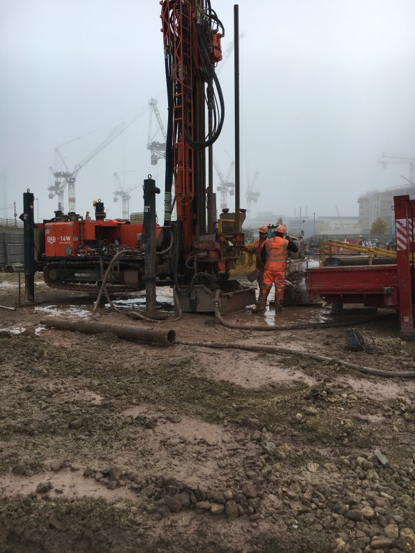
I am now three weeks into the construction of what will be the UK’s largest geothermal borehole field with 170x 200m deep Boreholes.
So here is the rough method of construction:
Install a 6m casing to protect the top of the borehole.

Using a specialist drilling rig, bore down 204m. Throughout the drilling, clean water is pumped into the borehole to reduce the temperature and help remove the spoil.
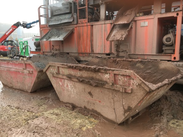
Once at depth, recover the drill rods. During this phase, the rejected water is collected and pumped to a mud-cleaner so it can be used to drill the next borehole or can be used to flush the borehole. The mud-cleaner adds a coagulant to help remove the fine solids and the slurry is then passed through two screens to remove the larger muds (On the let hand side of the mud-cleaner). Then the slurry is put through a centrifuge to remove the fines down to a size of 4microns. The clean water is then stored in the tanks along the bottom of the mud-cleaner or the reserve tank. The mud removed from the water is deposited in skips for off-site disposal.
Remove the muddy water and replace with clean water to reduce the buoyancy of the pipework. This is known as flushing.
Drop 2xpipe loops and a sacrificial pipe (green tremmy pipe) down the bore. To reduce the buoyancy of the pipework, the pipes are filled with water and a 230kg sacrificial weight is connected to the end. The pipe are installed using a specialist spool and a telehandler.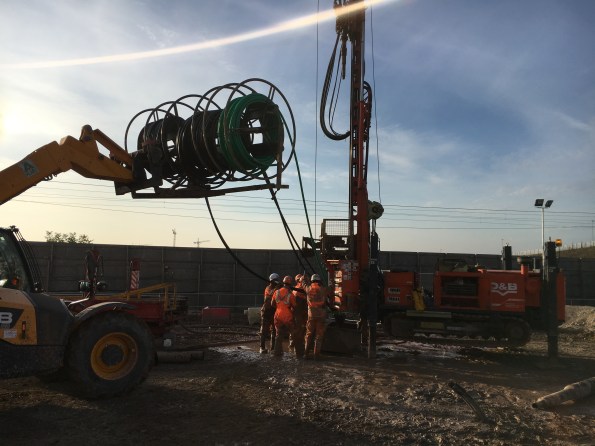
Pressure test the two pipe loops. Both u-shaped black pipes are tested at 8 bar for 30mins and then at 4 bar for 1 hour. Initially the pressure will dropped as the pipe expands and so the pressure is topped up. Towards the end of the test, a reduction in pressure points towards a leak.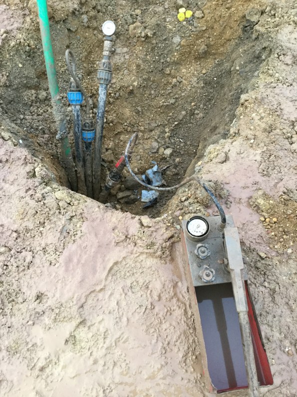
Flow test the pipe loops to check for blockages.
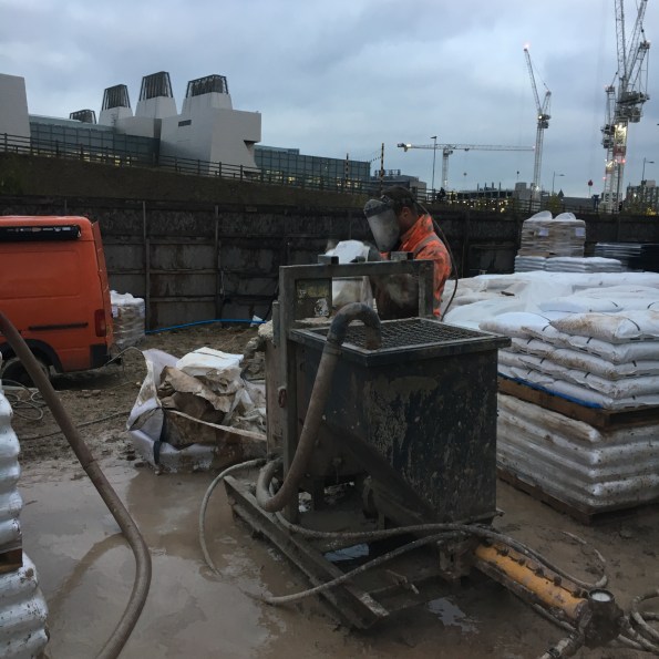
Backfill the borehole with thermal grout. This grout consists of bentonite and Chelmsford 52 silica sand with a silicon dioxide content of 97%+. Just enough water is added to the grout to make it ‘pumpable’. on my site we are using a 5.5 to 1 sand-to-bentonite ratio as this gives a thermal conductivity of 1.8W/Km2. The grout is mixed in a hopper and a sample is taken at random. The grout is pumped to the bottom of the borehole through the tremmy pipe which means that during filling, the water in the borehole is pushed up and rejected. This water is collected and pumped to the mud-cleaner to be cleaned and stored for future use.
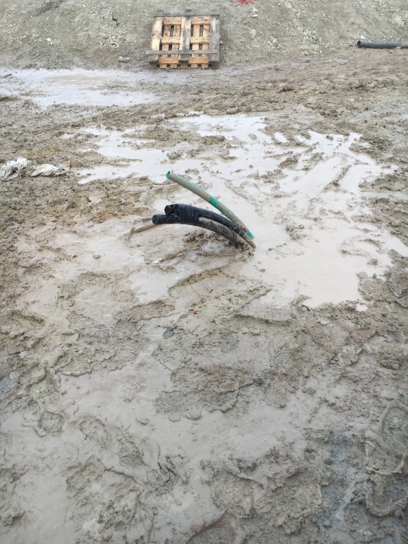
So that is how to construct a vertical heat exchanger for a Ground Source Heat Pump System. This is the end result ready for the horizontal pipework to be installed.
Dealing with Delays
The pace of work is speeding up as I reach the last month of my phase 2 attachment. Excellent news *insert sarcasm*.
The finished Bond Street East shaft structure should now be complete to accept tunnel ventilation equipment; cut-away graphic shown below.
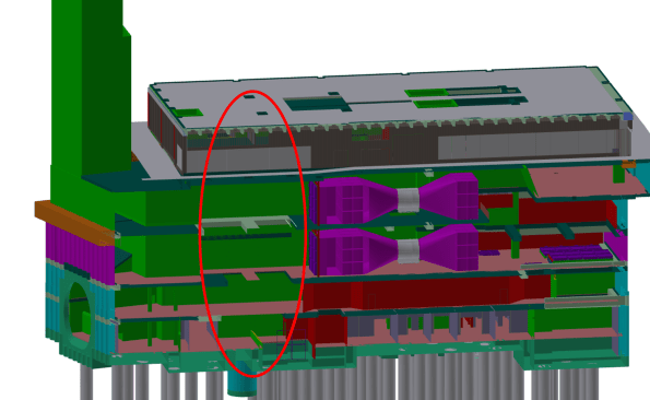
Graphic of the station structure; the ventilation equipment is shown in purple. The red oval denotes a gaping hole currently being filled by the civil contractor (see next photo).
The station structure was due to be complete by Aug 16; however the current site still has no roof, no lights, unsealed walls, etc; as shown in the figure below.
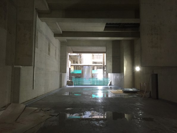
Tunnel vent fan room, missing the end wall (see previous image) and some weatherproofing, paint, permanent lights, etc….
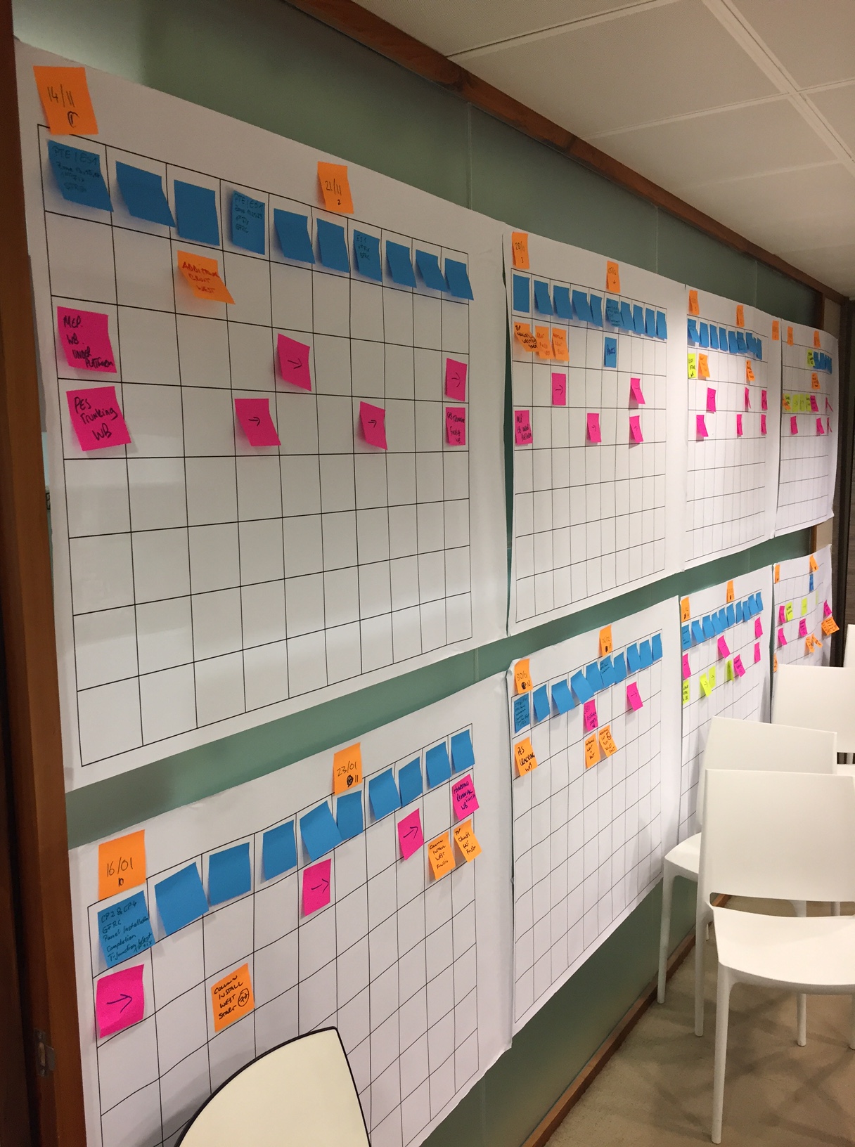
As a result of this delay the mechanical install (by ATCjv, my placement company) has to happen concurrently with the remainder of the civil works to make sure the trains can start running on time. The past few weeks have therefore been dominated by ‘collaborative planning’ to mitigate the civil contractor’s delays. I have eaten through a couple of packs of post-it notes and a lot of coffee to achieve an integrated 8-week plan that both sides agree on, see below:
This is all to achieve an interface control document (ICD); a kind of access and working contract where ATCjv mechanical works are installed in another contractors site Prime Contractor (PC) area. The process has also been a contractual minefield as the ATCjv works information assumed we had uninterrupted access to the entire structure.
The handover process should follow these steps:
- Civil contractor finishes structure.
- ATCjv accept structure and conduct a condition survey.
- Both sign an ICD and ATCjv start installing mechanical ventilation kit.
The actual process has been:
- Civil works delayed by >5 months.
- ATCjv have to start install to achieve Crossrail opening date, 2 weeks of collaborative planning commences.
- ATCjv rinse Crossrail (the taxpayer) for compensation events. ATCjv hide all their delays behind the civil contractors problems.
- ICD signed and mechanical install starts
It has not felt comfortable knowing that I have been part of the dodgy contractor game of blaming all our problems on a third party and getting a wedge of extra money out of the client/taxpayer…. welcome to construction.
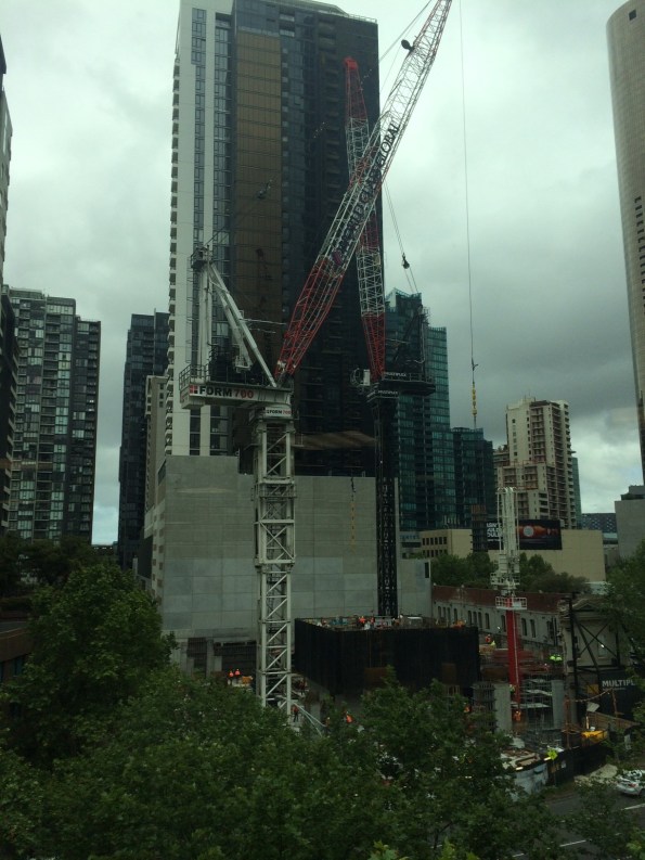
On a brighter note we have achieved actual mechanical installation at our Tottenham Court Road site; one gantry crane installed and commissioned on programme. However, I can’t help but feel out-done by the size of Jo’s man-size crane.

How to erect a 390D tower crane
I thought i’d put up a photo montage of the erection of our second tower crane in case anyone had ever wondered how it was done – the crane is a 390D self climbing core crane with a 25t lifting capacity. I know it will especially interest all you E&M engineers out there 🙂
- 4 double towers and the slew ring erected first


2. Cab and machine deck crane on top of slew ring


3. A frame is craned into place


4. 45m boom erected in the loading bay completed with the compulsory Multiplex signage, electrical fittings and the monkey. Note the red and white markings in accordance with pan ops regulations (as we will be protruding into the ‘flight zone’ for a period of three months).


5. Cables fitted to secure the boom and prepare for lifting load
Spot the fearless bloke running around the boom!!
6. The final product awaiting commissioning…
All in all this effort took two 2 days to complete over a rather gloomy weekend.
P.S Tom’s addition to my blog following his comment:
Temporary Works Inspections
The Temporary Works Design Manager thinks that I was appointed as the Temporary Works Supervisor (TWS) a couple of months ago, but in fact I refused to sign the appointment letter because I’m not wet behind the ears and I recognise a hospital pass when I see one. Apparently all of his underlings have refused to tell him this though. Regardless of the formalities I have in fact been fulfilling the role of TWC and TWS (the temporary works department are woefully under resourced) since we started on site.
The temporary works implementation process has now been issued so I have defined roles and responsibilities to discharge and am happy to take up my appointment (for the few weeks I have left on site). My first task was to formalise the temporary works inspection register, in accordance with the process that I helped draft, and to produce a template for other sites within the project to use.
Most of our work is managed by one main subcontractor (Volker Stevin or VSL) therefore we have stipulated that they submit their own inspection records to me and I will review their records and conduct spot checks on their paperwork and their temporary works elements on site.
As luck would have it I’ve poked a bit of a hornets nest with the first item that I chose to review, namely the access gangways that they use between shore and the jack up barges. The proprietary system used is shown on the pdf. They have improvised a fixing detail to the ancient timber on top of the jetty wall and have made no allowance within the design for any horizontal actions despite the gangways being used at an angle.
When I queried this with VSL they initially tried the “proprietary system” defence from personnel of increasing seniority (Senior Engineer, TWC, then Site Agent), followed by the “but we’ve only got it on site for a few more weeks” defence, followed by the submission of random bits of information that don’t actually answer the question I’ve asked them.
As “prove to me that this is safe” wasn’t working I have asked them for confirmation of what specification has been given for the fixing detail, what it should be fixed to, maximum angle of the gangway, restraint against sliding, detail of connections between gangways, and whether accidental actions been considered. Unsurprisingly the site team could answer none of these questions and have farmed them out to their designers. Which leaves me with the interesting question of what to do in the meantime, as no-one apart from me really seems to want to push the issue for fear it may delay the works.
Note: The image below is actually an earlier image where the gangway spanned from shore to barge and there were no issues with the use of the gangway. Currently the JUB is further out and one gangway spans from the jetty to the inner pile line (sloping down as the piles are lower than the jetty) and another gangway from the piles up to the JUB. I will upload a more recent picture when I can get back up in the cage, and also a close up of the improvised fixing detail on the jetty. [Picture updated 11/11/16]


One for the civils – concrete
We are having some issues with the supply of concrete meeting the specification (its under strength) and I am curious as to why and how this could have been managed better. I don’t think the contracts are robust enough to manage the risk of getting it wrong as we appear to be dealing with the aftermath of it all rather than our subcontractor. Tail wagging the dog scenario. The questions goes out there as to whether anyone else has had any major dramas with their concrete not meeting the required standard and have you had any issues with your supply chain? If so, what has been done about it?
Repeat answers from the whatsapp group greatly appreciated 🙂
What I wish I knew before starting phase 2!
This kind of links in to AER3 and a discussion that the civils were having on WhatsApp. I will leave the concrete supplier conundrum to Jo. But I hope my fellow Phase 2 PETs will all add comments.
I wish I had agreed from the outset that I would do 6 months on the site team then 6-8 weeks with the commercial team.
I also wish I had more of a data base of TMRs and AERs to baseline against.
