Archive
How to construct a geo-thermal borehole
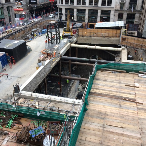
I am now three weeks into the construction of what will be the UK’s largest geothermal borehole field with 170x 200m deep Boreholes.
So here is the rough method of construction:
Install a 6m casing to protect the top of the borehole.

Using a specialist drilling rig, bore down 204m. Throughout the drilling, clean water is pumped into the borehole to reduce the temperature and help remove the spoil.
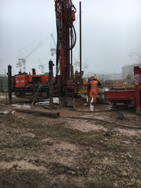
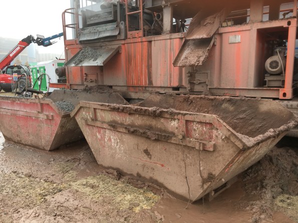
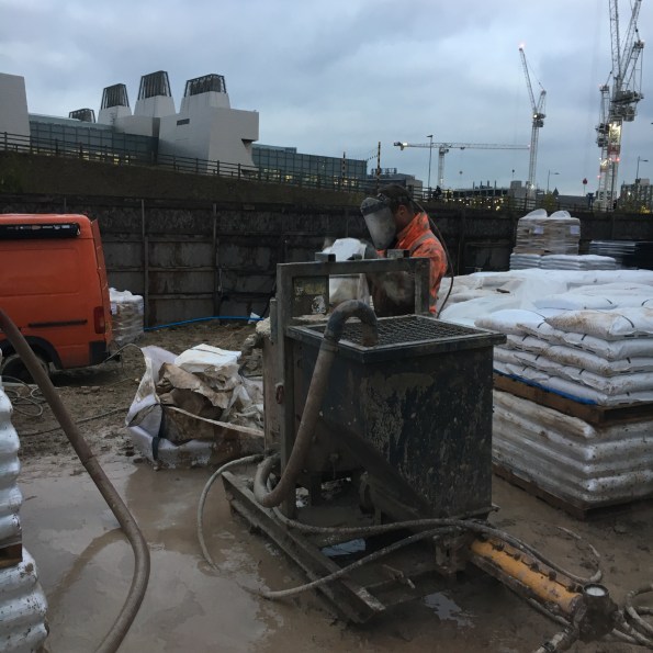
Once at depth, recover the drill rods. During this phase, the rejected water is collected and pumped to a mud-cleaner so it can be used to drill the next borehole or can be used to flush the borehole. The mud-cleaner adds a coagulant to help remove the fine solids and the slurry is then passed through two screens to remove the larger muds (On the let hand side of the mud-cleaner). Then the slurry is put through a centrifuge to remove the fines down to a size of 4microns. The clean water is then stored in the tanks along the bottom of the mud-cleaner or the reserve tank. The mud removed from the water is deposited in skips for off-site disposal.
Remove the muddy water and replace with clean water to reduce the buoyancy of the pipework. This is known as flushing.
Drop 2xpipe loops and a sacrificial pipe (green tremmy pipe) down the bore. To reduce the buoyancy of the pipework, the pipes are filled with water and a 230kg sacrificial weight is connected to the end. The pipe are installed using a specialist spool and a telehandler.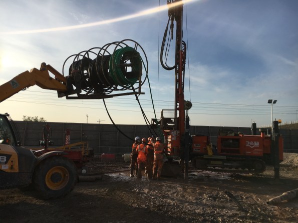
Pressure test the two pipe loops. Both u-shaped black pipes are tested at 8 bar for 30mins and then at 4 bar for 1 hour. Initially the pressure will dropped as the pipe expands and so the pressure is topped up. Towards the end of the test, a reduction in pressure points towards a leak.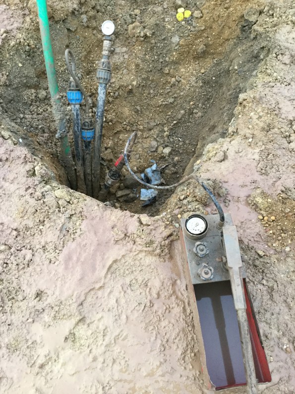
Flow test the pipe loops to check for blockages.
Backfill the borehole with thermal grout. This grout consists of bentonite and Chelmsford 52 silica sand with a silicon dioxide content of 97%+. Just enough water is added to the grout to make it ‘pumpable’. on my site we are using a 5.5 to 1 sand-to-bentonite ratio as this gives a thermal conductivity of 1.8W/Km2. The grout is mixed in a hopper and a sample is taken at random. The grout is pumped to the bottom of the borehole through the tremmy pipe which means that during filling, the water in the borehole is pushed up and rejected. This water is collected and pumped to the mud-cleaner to be cleaned and stored for future use.
So that is how to construct a vertical heat exchanger for a Ground Source Heat Pump System. This is the end result ready for the horizontal pipework to be installed.
Dealing with Delays
The pace of work is speeding up as I reach the last month of my phase 2 attachment. Excellent news *insert sarcasm*.
The finished Bond Street East shaft structure should now be complete to accept tunnel ventilation equipment; cut-away graphic shown below.
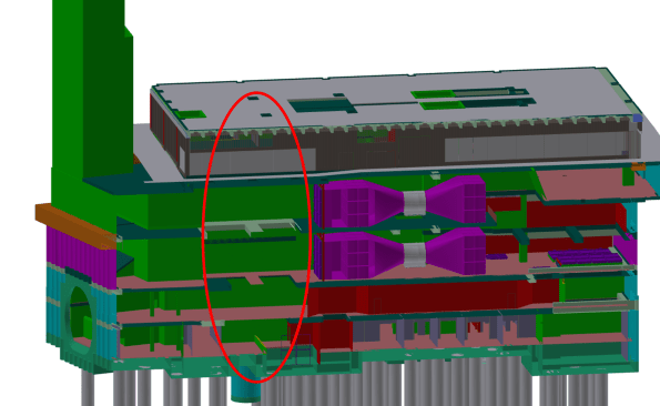
Graphic of the station structure; the ventilation equipment is shown in purple. The red oval denotes a gaping hole currently being filled by the civil contractor (see next photo).
The station structure was due to be complete by Aug 16; however the current site still has no roof, no lights, unsealed walls, etc; as shown in the figure below.
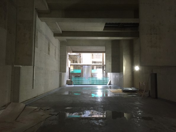
Tunnel vent fan room, missing the end wall (see previous image) and some weatherproofing, paint, permanent lights, etc….
As a result of this delay the mechanical install (by ATCjv, my placement company) has to happen concurrently with the remainder of the civil works to make sure the trains can start running on time. The past few weeks have therefore been dominated by ‘collaborative planning’ to mitigate the civil contractor’s delays. I have eaten through a couple of packs of post-it notes and a lot of coffee to achieve an integrated 8-week plan that both sides agree on, see below:

This is all to achieve an interface control document (ICD); a kind of access and working contract where ATCjv mechanical works are installed in another contractors site Prime Contractor (PC) area. The process has also been a contractual minefield as the ATCjv works information assumed we had uninterrupted access to the entire structure.
The handover process should follow these steps:
- Civil contractor finishes structure.
- ATCjv accept structure and conduct a condition survey.
- Both sign an ICD and ATCjv start installing mechanical ventilation kit.
The actual process has been:
- Civil works delayed by >5 months.
- ATCjv have to start install to achieve Crossrail opening date, 2 weeks of collaborative planning commences.
- ATCjv rinse Crossrail (the taxpayer) for compensation events. ATCjv hide all their delays behind the civil contractors problems.
- ICD signed and mechanical install starts
It has not felt comfortable knowing that I have been part of the dodgy contractor game of blaming all our problems on a third party and getting a wedge of extra money out of the client/taxpayer…. welcome to construction.
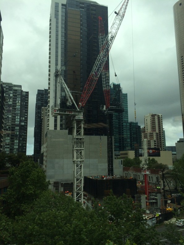
On a brighter note we have achieved actual mechanical installation at our Tottenham Court Road site; one gantry crane installed and commissioned on programme. However, I can’t help but feel out-done by the size of Jo’s man-size crane.

How to erect a 390D tower crane
I thought i’d put up a photo montage of the erection of our second tower crane in case anyone had ever wondered how it was done – the crane is a 390D self climbing core crane with a 25t lifting capacity. I know it will especially interest all you E&M engineers out there 🙂
- 4 double towers and the slew ring erected first


2. Cab and machine deck crane on top of slew ring


3. A frame is craned into place


4. 45m boom erected in the loading bay completed with the compulsory Multiplex signage, electrical fittings and the monkey. Note the red and white markings in accordance with pan ops regulations (as we will be protruding into the ‘flight zone’ for a period of three months).


5. Cables fitted to secure the boom and prepare for lifting load
Spot the fearless bloke running around the boom!!
6. The final product awaiting commissioning…
All in all this effort took two 2 days to complete over a rather gloomy weekend.
P.S Tom’s addition to my blog following his comment: