How to construct a geo-thermal borehole
I am now three weeks into the construction of what will be the UK’s largest geothermal borehole field with 170x 200m deep Boreholes.
So here is the rough method of construction:
Install a 6m casing to protect the top of the borehole.

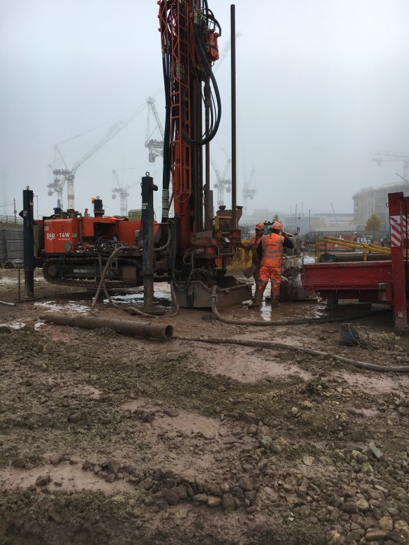
Using a specialist drilling rig, bore down 204m. Throughout the drilling, clean water is pumped into the borehole to reduce the temperature and help remove the spoil.
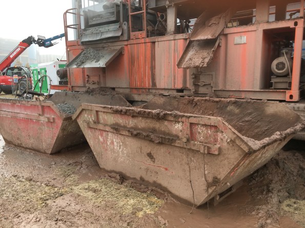
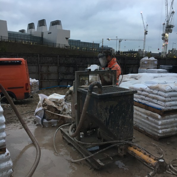
Once at depth, recover the drill rods. During this phase, the rejected water is collected and pumped to a mud-cleaner so it can be used to drill the next borehole or can be used to flush the borehole. The mud-cleaner adds a coagulant to help remove the fine solids and the slurry is then passed through two screens to remove the larger muds (On the let hand side of the mud-cleaner). Then the slurry is put through a centrifuge to remove the fines down to a size of 4microns. The clean water is then stored in the tanks along the bottom of the mud-cleaner or the reserve tank. The mud removed from the water is deposited in skips for off-site disposal.
Remove the muddy water and replace with clean water to reduce the buoyancy of the pipework. This is known as flushing.
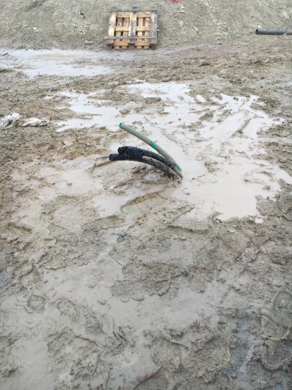
Drop 2xpipe loops and a sacrificial pipe (green tremmy pipe) down the bore. To reduce the buoyancy of the pipework, the pipes are filled with water and a 230kg sacrificial weight is connected to the end. The pipe are installed using a specialist spool and a telehandler.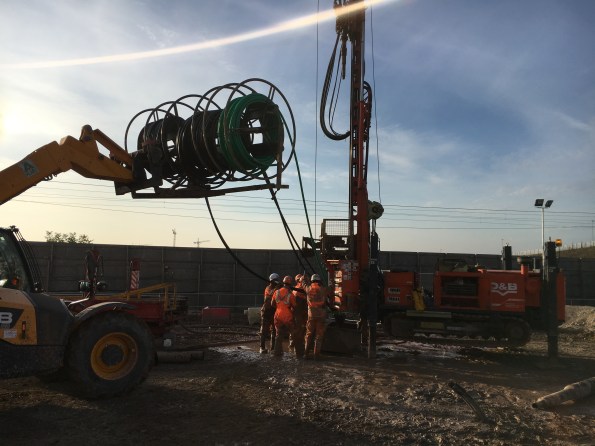
Pressure test the two pipe loops. Both u-shaped black pipes are tested at 8 bar for 30mins and then at 4 bar for 1 hour. Initially the pressure will dropped as the pipe expands and so the pressure is topped up. Towards the end of the test, a reduction in pressure points towards a leak.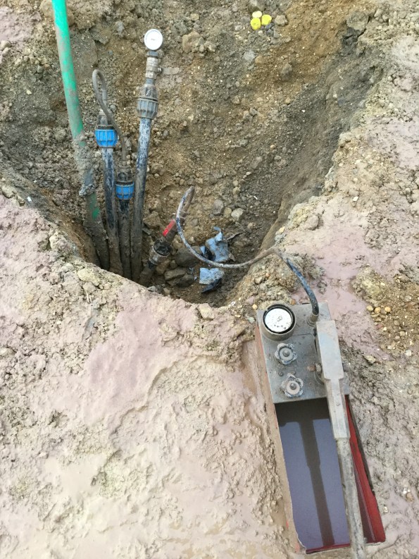
Flow test the pipe loops to check for blockages.
Backfill the borehole with thermal grout. This grout consists of bentonite and Chelmsford 52 silica sand with a silicon dioxide content of 97%+. Just enough water is added to the grout to make it ‘pumpable’. on my site we are using a 5.5 to 1 sand-to-bentonite ratio as this gives a thermal conductivity of 1.8W/Km2. The grout is mixed in a hopper and a sample is taken at random. The grout is pumped to the bottom of the borehole through the tremmy pipe which means that during filling, the water in the borehole is pushed up and rejected. This water is collected and pumped to the mud-cleaner to be cleaned and stored for future use.
So that is how to construct a vertical heat exchanger for a Ground Source Heat Pump System. This is the end result ready for the horizontal pipework to be installed.

Nice summary Gary.
Gary
Is it definitely clean water pumped in to support the excavation during drilling?
The de-sander and de-silter are identical to the bits of kit we use in our Bentonite farm. From my limited understanding, I would have thought the properties of bentonite would have provided better support too?