Archive

Archive for December, 2016

If a picture paints 1000 words, then this is a 2002 word summary of 2016 on the St George Hospital Project…

20/12/2016 1 comment

April:

april-2016

Dec:

dec-2016

Merry Christmas and Happy New Year.

James

Categories: Uncategorized

This engineer built a 3D model. What he did next will SHOCK you…

20/12/2016 3 comments

Now that I have reeled you in with a click bait headline I will now proceed to chat about some fairly mundane Phase 3 stuff.

I have recently started Phase 3 with Wentworth House Partnership (Keltbrays’ Temporary Works department). On day one I was given the task of conducting a CAT 3 check on a facade retention system for a hotel in Burma. Essentially a large steel frame has been designed to hold up a wall and I need to check the design to ensure that it is safe and can be built (for the civils out there this is effectively like doing Ex STEEL but with trickier parts…..and yes I have already cursed whoever wrote the Eurocodes as they are as hard to follow as ever!).

To cut two weeks of steel design short I am just going to talk about one part of the process which is turning a complex model into a simple one in order to analyse it. In this instance I was trying to establish what load the piles supporting the facade retention system (and the facade) would be experiencing. The complex model is a 3D model that I built on a programme called Tekla Structural Designer (this is a lot like STAAD Pro but I think it is a bit more user friendly). I built the model by meticulously studying the engineer detail drawings and the associated CAD files so that I could turn a 2D drawing into a 3D model.

screenshot-1

A screen shot of the Facade Retention System model (please note that this is just a section of a much larger frame)


I then added wind loading to the frame and  was therefore able to analyse the frame within the model and get the vertical reactions at the supports due to the wind loading. I then created a separate model to analyse the effect of all the loading (wind loading, weight of facade, weight of Facade Retention System and self weight of the concrete slab that the facade and the retention system were sitting on) on the piles below.

screenshot-4

a view of the 3D modle I used to analyse the effect of all loading on the piles

From this separate model I was able to use the programme to view the total reactions on the piles and therefore use this value to check is the piles were adequate.

A 3D model is a fairly complex model and I needed to verify that the results the model was showing me were accurate and could be trusted. Consequently I had to simplify the model so that I stood a chance of being able to analyse it by hand. I decided to model the problem as a beam with 3 supports (the supports being the piles). I then applied point loads for the weight of facade, weight of facade retention system and wind loading and applied UDLs for the self weight of the concrete slab. Using moment distribution I was able to find the reactions at each of the supports and was please to see that they were fairly similar to those that the 3D model was giving me.img_12871

The problem ‘simplified’. 


The lesson learned from all this is that what appears to be quite a complex problem can be simplified into a relatively simple problem that can be used to verify real world issues (assuming you can remember how to do a moment distribution…..it took me far longer then i’m proud of. Good job I kept my structures notes!). The basic principles taught on Phase 1 have paid dividends and I am still managing to maintain my thin veneer  of competency.


Categories: Uncategorized

Farewell Multiplex

20/12/2016 1 comment

So my time with Multiplex is at an end.  I have been on the Australia 108 project from Feb 16 and have had responsibility in various aspects of the project delivery, and nosed my way into the rest to maximise my learning opportunities.  Site activities have included, large bored piles, CFA piles, basement excavations, retaining walls, ground anchors, jet grouting, pile caps and capping beams, pre-cast concrete, post tensioned concrete and lots of reinforced concrete in the form of the core, slabs and columns.  I have also been responsible for the design coordination and delivery of the structural steel package, the car slider package as well as early construction methodology for the starburst.

At present state, the core has been poured to Level 6 with a hope to pour to Level 7 pre-Christmas, and the Level 2 slab has just been completed.

My time on A108 has been eventful and rewarding yet frustrating and challenging at the same time.  It has been an invaluable opportunity with many positive experiences as well as some negative but  I have learned something from each and I am a better engineer, leader and manager because of it.   Phase 2 has presented significant opportunities to broaden my experience, test my technical knowledge, managerial and communication abilities.

Recommendations

To Phase 1 students I would recommend the following:

  1.  Project selection  – understand the project program and where the project will be within that program during your time on site.  This will dictate what opportunities are available to you.
  2. Ownership – MPX struggled to understand the aim of my attachment and I have strongly had to drive my attachment to make certain I got the depth and breadth of experience I needed.
  3. Review – genuinely use the AERs and CPD record to review your journey to achieving your attributes.  Where you have gaps, seek out other opportunities and experiences to ensure you get the most of your attachment.
  4. Preparation – trust that Phase 1 prepares you well, because it does.


Categories: Uncategorized

A fresh start

Background.  Since February 2016, I have been employed by Multiplex on the Brisbane Casino Towers (BCT) project, in South Brisbane.  I left the BCT site on 28 November 2016 and started my Phase 3 attachment, at Multiplex Head Office, Queensland, Australia. I am currently employed in the design team working to the only chartered engineer in Multiplex Queensland. I won’t cover specific technical issues as Andy B has already done an excellent article on his beam design.

Experience so far.  After completing the preparation for the removal of the retaining wall restraints at BCT, I moved to the Head Office Engineering Design Team.  Since I have arrived I have mostly been providing project support to the Jewel project on the Gold Coast and my old site BCT but, I have done preliminary work for the New Business Team.


Roles and responsibilities. I am involved in providing technical advice to three areas of the business.

  •  Project support. Core business of the design team is to provide assistance in resolving issues with the projects’ design consultants. The design team provide oversight capability to designers ensuring quality is maintained, designed to fit for purpose, are constructible and cost-effective. The early identification of design risks, is critical to maintaining the projects’ programmes.
  • New business. The design team has considerable day-to-day contact with the new business team. They technically review all designs prior to tenders being submitted. They provide oversight on design consultants’ rates, comment technically on sub- contractors’ initial bids and conduct preliminary assessment on the suitability of designs. Risk identification is an essential part of this task. Alerting the new business team to potential hazards early on in the tender process allows risks to be suitably managed. Recently they have had significant involvement in the geotechnical assessment of future projects.
  • Novel technology. Multiplex employee a group of academic engineers to come up with novel solutions to engineering problems. However, they are not often best placed to understand the limitations of the project. The role of the design team is therefore to interpret the requirements of the site and project teams and brief the academics accordingly.

Stakeholders.  Given that the Design team are often called in when an issue has been identified.

  • New Business Team.  Supportive and routine relationship.
  • Consultants.  Cautious and sometime hostile.
  • Project Teams.  Supportive but cautious of exposing their own errors to head office.
  • Sub-contractors.  Neutral to hostile compared to the details of the issue.
  • Clients.  Generally cautious between neutral and hostile.

Current Projects.  There are several ongoing projects but I will concentrate on the ones I am working on now.

img_5789

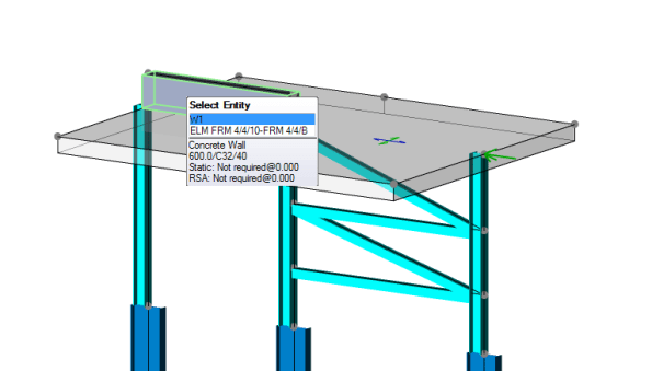
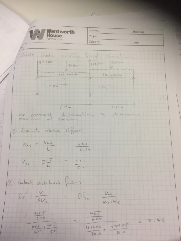
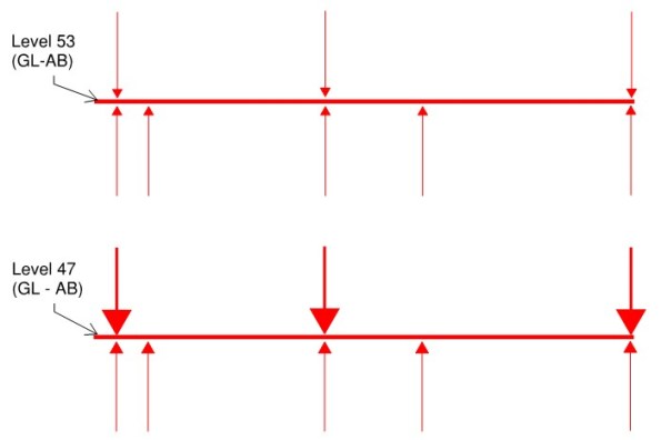
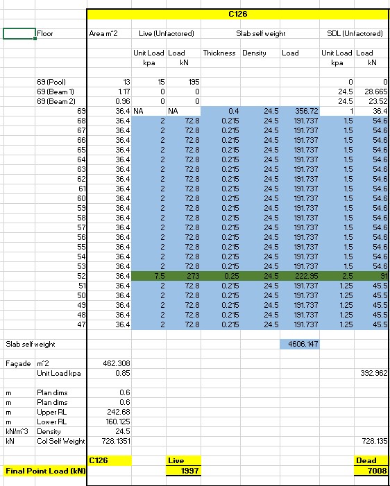
BCT continues to have issues – What happens when a basement column fails to achieve strength (100 MPa)

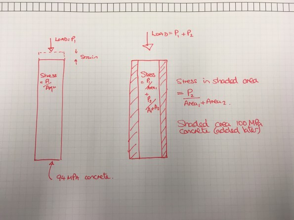
Brisbane Casino Towers (BCT).  ($108M) My old site continues to be an utter disaster.  The latest debacle is that the concrete strength is failing to come up to strength so remedial works are going to hare to be made to the basement columns.  The Johnny age 5 sketch was an attempt to show why you have to allow for the current strain when determining the extra amount of concrete to add around a column that has not reached strength. Long story short the stress from the half built structure is already in the 94 MPa column and any additional load is shared between the existing column and the extra concrete.  An interesting couple of days on this one – pouring through Australian Standards and contracts.  BLUF – the concrete supplier has been very naughty and needs to fix this and compensate Multiplex for time lost – @ $35,000 a day – very expensive!

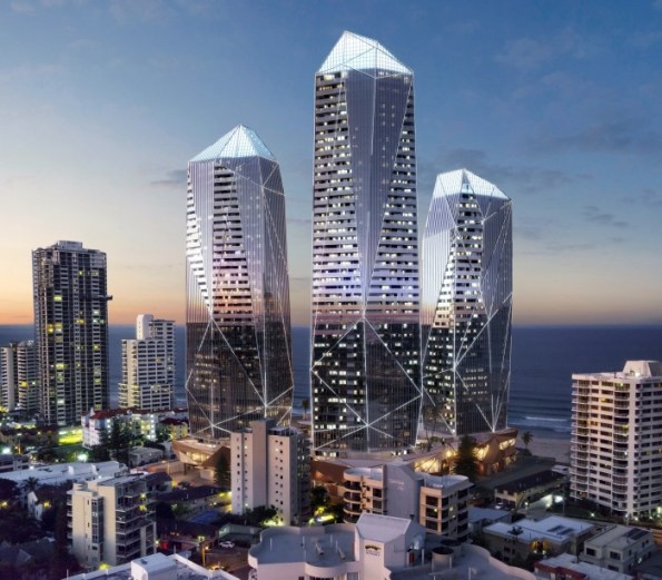
Jewel.  ($600M) The Jewel will be Australia’s largest beachfront mixed-use development and the first absolute beach front development on the Gold Coast in more than 30 years.

The luxury development is located on Old Burleigh Road in Broadbeach, the three-tower development will include a three-level podium, a six-star hotel comprising 171 suites and 512 one, two and three-bedroom luxury apartments and premium residences. The development will feature three levels of basement parking to accommodate 816 cars.


Problem 1.  I have been conducting a value management exercise on the design of the slabs.  I have cut the reinforcement by a third at Podium Level 2.  I have cut several slab thicknesses down by 25%.  I am planning to do a TMR on this value management exercise and why consultants over engineer designs! (more to follow).

Problem 2.  The Towers are connected by steel foot bridges which presents a problem during wind loading and earthquakes.  The footbridges need to be able to accept deflections of up to 850 mm because the towers will move independently.  Currently ther is only an expansion gap of 50 mm so this needs addressing.  Additionally, the last slab level to connect the towers (ground) becomes a tension member during an earthquake and this needs to be allowed for with extra reinforcement so I need to conduct some checks to ensure this is done.

151207__jewel__v26__1454451540.jpg

Future Business.  Key new Business that we are looking to win.  

Queen's Wharf.png

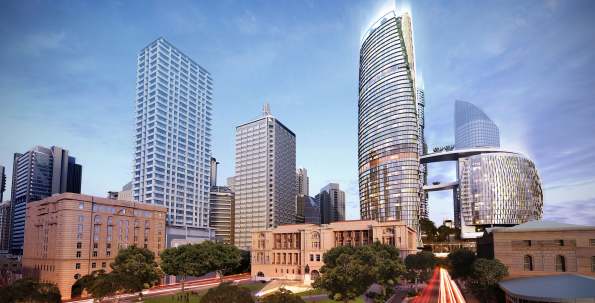
Queen’s Wharf.  ($1B+) Queen’s Wharf Brisbane has the capacity to realise Brisbane’s growth and profile aspirations by delivering a truly-place defining precinct with significant transformational impacts on Queensland’s economy, jobs, tourism, visitation, liveability and image.

The Destination Brisbane Consortium vision for Queen’s Wharf Brisbane is to design, build and manage with excellence a place for which Brisbane will be renowned and its people immensely proud.

The Destination Brisbane Consortium will deliver an iconic redevelopment at the city’s heart that invigorates the entire precinct and delivers striking landmark architecture as part of the best integrated resort in Australia.

Destination Brisbane Consortium’s development of the Queen’s Wharf Brisbane precinct will deliver transformational impacts on the Queensland economy through job creation, training and tourism.

The Development of Queen’s Wharf Brisbane will include the following key features:

  • The iconic signature “Arc” building
  • A spectacular Sky Deck, giving stunning views of the Brisbane River and skyline, complete with restaurants and bars
  • The repurposing of existing (Treasury casino and Hotel) heritage buildings to maximize their contribution to Brisbane
  • Five premium hotel brands, including the world renowned Ritz-Carlton and Rosewood brands plus the introduction of Brisbane’s first six star hotel
  • Infinity resort pool overlooking the Brisbane River and Southbank
  • Fifty restaurants and bars, from hatted fine dining to pop-up cafes
  • Moonlight roof top cinema, black tie event space and a variety of outdoor lifestyle opportunities
  • Cohesive Bridge-to-Bridge precinct, integrating heritage and new architecture
  • 12 football fields of public event space.

toowong-image
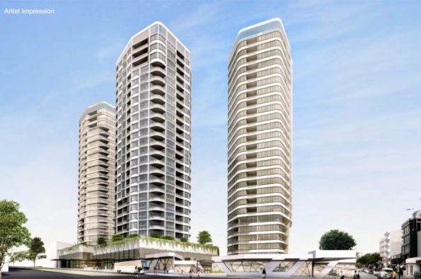
Stockland Toowong.  ($200M)  Three 25 storey residential towers located at 23-79 High Street Toowong, on a 1.3 hectare site, currently the site of a Woolworths supermarket.  Interestingly from a geotechnical point of view the area is situated in very low to very high strength phyllite and alluvium deposits. The basement will be below the water table and due to the proximity of other buildings there will not be any underslab drainage so there is significant hydrostatic uplift on the ground bearing slab.  The basement is going to be a nightmare to build.  I am the technical lead for this project – so no doubt more to follow.  Stages.  The project will be split into three stages.  With sales from the first stage being essential to provide funding for the others.

  • Stage 1: 25 storey residential tower (184 units), with ground level retail uses (1,354m2 GFA) and an expansive plaza, and associated parking and servicing. This has a 3 storey car park basement.
  • Stage 2: 25 storey residential tower (172 units) fronting High Street, ground level retail uses (328m2 GFA), expansive podium private open space plaza and associated parking.
  • Stage 3: 25 storey residential tower (174 units) fronting High Street, ground level retail uses (267m2 GFA), expansive podium private open space plaza and associated parking.
Categories: Uncategorized

Managing Temporary Works Risk

13/12/2016 2 comments

As most students will have noted on phase 2, TW can be a particularly high risk element of any construction project. For the last few months, in addition to my other responsibilities, I have been involved inspecting items as they are installed and during their ongoing use.

On a high rise building, a failure of TW in an unfortunate location can have exceptionally serious consequences, because people or items can potentially fall from very significant heights. As the Principle Contractor  we are therefore supposed to provide a very thorough secondary control system. This involves scrutinising and inspecting the TW’s designed and installed by our relevant sub – contractors, who officially carry liability for their own systems. I have noted that more often than not TW are not installed exactly to the approved design as the guys on site have a habit of making  unapproved adjustments. Whilst this is not acceptable, in many cases the implications of a failure are minor.

This morning whilst conducting a check of a TW system installed by our concrete contractors a colleague and I identified an issue that worried us significantly enough that I have decided to write a blog on it. The images below shows the  design of a temporary access walkway platform suspended between two walls of our reinforced concrete core. It spans over a permanent lift shaft at level 10. To be clear, below this TW structure is a 10 storey, plus 15m of additional basement, vertical drop. i.e. If it fails and someone is on it at that unfortunate moment, that person is falling unobstructed down a vertical shaft for the best part of 32m, from floor 10 into our basement.

tw-general-arrangement

primary-beam-support-elevation

You can therefore probably understand why I got very upset when it became apparent (whilst I was stood on it) that this system  had been installed, declared operational and used by numerous operators on site without the most basic conditions being met:

  • The design process being completed in full with a final check signed off as status A by MPX (Principle Contractor)
  • The installation being inspected to assure conformance with design by a competent MPX TW supervisor
  • A permit to load certificate being signed by a competent person

It turns out they built this over a weekend and started using it immediately without anyone checking the quality of the installation. Even the sub-contractors own TW supervisor (The first layer of inspection) had not checked and signed off this installation prior to its use. In this case two of the key management safety layers had been completely ignored; highly upsetting when you consider that a failure of this system would almost certainly result in a fatal accident.

tw-platform

The TW platform prior to the installation inspection – Structural components cannot be easily accessed or inspected


tw-inspection-primary-and-secondary-beam

TW Primary and Secondary Beam Installation Check

As the images above show, in this case we were eventually able to access the TW structure and confirm it had been installed correctly. Our main issue is that this process did not proceed us standing on it over a lethal void.

The TWprocedure exists for a very good reason. To provide multiple layers of review and inspection in order to best mitigate the risk of a failure and a subsequent accident. It is quite alarming how often  sub-contractors prioritise programme and task progress at the expense of a thoroughly enforced, critical  safety procedure, particularly on such high risk TW schemes.


Categories: Uncategorized

Phase 3: Week 1…

Since starting my Phase 3 attachment with Robert Bird Group last week I have been tasked with evaluating the current conceptual design of a 70 storey building.  The main effort in this exercise was to see if the column layout could be revised to maximise floor space in the upper floors.  An impression of the structure is in the figure below.

broo-impression-png

The current design sees a consistent column layout between Ground Floor and Level 53.  Above Level 53, the layout changes to maximise floor space in the upper levels.  My task was to evaluate whether the Level 53 transfer beams, would still work if they were moved to Level 47, without changing their geometry. The main consideration here is the additional load on the transfer beams caused by Levels 47 to 53.  An illustration showing the approximate location of the transfer beams is in the figure below.

broo-elevation-png

A plan of the structure is below.  The two transfer beams have been highlighted.

broo-plan

A simple sketch indicating the loads acting on one of the two beams is below.  There are three columns acting as point loads on the beam, with five supports below the beam.  Moving the beam lower in the structure simply changes the magnitude of the loads.

broo-fbd

Once I understood the intent, I set about analysing the loads.  I captured the loads acting on each floor and multiplied them by the area of that floor being supported by the columns in question. This allowed me to work out the magnitude of the point loads acting on the beam.  An example of my load analysis for one of the columns is below.

broo-loads

I then added the UDL acting on the beam and checked to see if the beam could perform under the new design loads.  This check was performed using a software package, commonly used by Robert Bird Group – ‘RAPT’.  RAPT is not too dissimilar to STAAD Pro.

broo-verification

After running the check, I was able to confirm that the transfer beams could continue to perform as designed, without changing their geometry.

A relatively simple task, ideal for dusting off the Structural Analysis notes.

Categories: Uncategorized