This engineer built a 3D model. What he did next will SHOCK you…
Now that I have reeled you in with a click bait headline I will now proceed to chat about some fairly mundane Phase 3 stuff.
I have recently started Phase 3 with Wentworth House Partnership (Keltbrays’ Temporary Works department). On day one I was given the task of conducting a CAT 3 check on a facade retention system for a hotel in Burma. Essentially a large steel frame has been designed to hold up a wall and I need to check the design to ensure that it is safe and can be built (for the civils out there this is effectively like doing Ex STEEL but with trickier parts…..and yes I have already cursed whoever wrote the Eurocodes as they are as hard to follow as ever!).
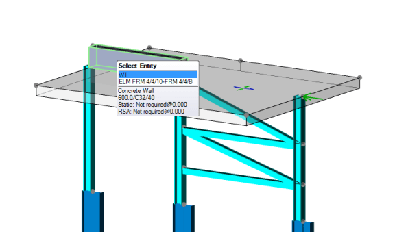
To cut two weeks of steel design short I am just going to talk about one part of the process which is turning a complex model into a simple one in order to analyse it. In this instance I was trying to establish what load the piles supporting the facade retention system (and the facade) would be experiencing. The complex model is a 3D model that I built on a programme called Tekla Structural Designer (this is a lot like STAAD Pro but I think it is a bit more user friendly). I built the model by meticulously studying the engineer detail drawings and the associated CAD files so that I could turn a 2D drawing into a 3D model.

A screen shot of the Facade Retention System model (please note that this is just a section of a much larger frame)
I then added wind loading to the frame and was therefore able to analyse the frame within the model and get the vertical reactions at the supports due to the wind loading. I then created a separate model to analyse the effect of all the loading (wind loading, weight of facade, weight of Facade Retention System and self weight of the concrete slab that the facade and the retention system were sitting on) on the piles below.
a view of the 3D modle I used to analyse the effect of all loading on the piles
From this separate model I was able to use the programme to view the total reactions on the piles and therefore use this value to check is the piles were adequate.
A 3D model is a fairly complex model and I needed to verify that the results the model was showing me were accurate and could be trusted. Consequently I had to simplify the model so that I stood a chance of being able to analyse it by hand. I decided to model the problem as a beam with 3 supports (the supports being the piles). I then applied point loads for the weight of facade, weight of facade retention system and wind loading and applied UDLs for the self weight of the concrete slab. Using moment distribution I was able to find the reactions at each of the supports and was please to see that they were fairly similar to those that the 3D model was giving me.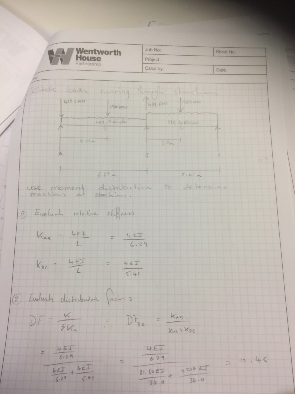
The problem ‘simplified’.
The lesson learned from all this is that what appears to be quite a complex problem can be simplified into a relatively simple problem that can be used to verify real world issues (assuming you can remember how to do a moment distribution…..it took me far longer then i’m proud of. Good job I kept my structures notes!). The basic principles taught on Phase 1 have paid dividends and I am still managing to maintain my thin veneer of competency.

The title really did work mate 🙂 Good effort on the moment distribution.
I fell for head line…I feel both stupid for falling for it and also more educated having read the whole blog.
What was your plan is the model and hand calc had been different? Which one would you have trusted? I spent a week with the mechanical designers from my project and when I asked if they did any hand calcs to check the results from their models they looked at me as if I had two heads and was speaking Swahili! It was the same when I went to the hydraulic designers – they had complete confidence in their models.
James, to be honest I would have trusted the hand calcs over the model as I have only just learned how to use Tekla so there are a lot of variables that could go wrong.
Its interesting that you say the mechanical designers do not back up their model with calcs. Everyone at Wentworth House submits calc sheets alongside any 3D models during the design process. Whilst 3D modelling is trusted to deliver a sensible result they will always have a check to confirm. Although the calc sheets are rarely done by hand (apparently i’m still oldskool in that respect!),they are primarily done on a programme called TEDDS which is effectively a word document that will calculate any equation you type into it and produce a nice looking results table for you.