Archive
Psychometric charts are not all straight lines…and other things that I have learnt about Mechanical Systems.
Summary of Design Secondment to Fredon.
Introduction
As I am not completing a typical Ph2/Ph3 attachment, I have been trying to bolster my B (Design) competencies by undertaking short design focused secondments away from Mulitplex. Fredon are the mechanical sub-contractor for the St George Hospital Project and as such design and install all the mechanical building services. In total I spent 5 days with Fredon at their design office. I benefited from this design secondment in 3 areas:
- Extending technical knowledge of services engineering.
- Reinforcement of theory and knowledge from PET course.
- Practical aspects and implications of theory.
Aim of secondment.
The aim of the secondment to Fredon was to develop a thorough understanding of the processes used for the design of mechanical building services – starting out with heat load modelling and concept design then eventually finishing with the detailed design of all the necessary elements of the system ready for installation.
Timetable.
- 5 Sept 16: Overview, heat load modelling using CAMEL.
- 6 Sept 16: Heat load modelling using CARRIER, air distribution and smoke exhaust systems.
- 12 Sept 16: Psychrometrics.
- 13 Sept 16: Cooling, balancing and valves
- 22 Sept 16: Electrical and building management. Value engineering
Key documents.
- AS1668-1: The use of ventilation and air conditioning in buildings – Fire and smoke control in multi-compartment buildings.
- AS1668-2: The use of ventilation and air conditioning in buildings – Ventilation design for indoor air contaminant control.
- AS3000: Electrical installations.
- AS4254: Ductwork for air-handling systems in buildings.
- BSIRA Rules of thumb.
- TS11: New South Wales Engineering Services and Sustainable Development Guidelines
Overview of secondment.
Design fundamentals. The key considerations before starting the mechanical design are:
- Thermal zones and environmental conditions. Australia is split into 8 thermal zones, each one with its own requirements for typical equipment and insulation. For example Tasmania requires heating, insulation and limited cooling, whilst Cairns requires significant cooling and no heating. In Australia the peak thermal loading occurs on the NW face of a building at 1500.
- Occupancy and use of building. AS1668 covers the requirements for certain building usages – for hospitals a theatre must have 20 air changes, the ED only requires 10. The occupancy of the building also changes the acceptable envelope of conditions.
- Type of building. For example in residential construction there are 5 grades of building. Grade 1 is the highest quality, Grade 5 the lowest. Clients and end users of the former will have far higher expectations of performance and quality than the latter where merely conformance with minimum AS1668 standards is required.
- Scale of the project. The scale and the life span of the project are key variables in the selection of mechanical equipment – at the smallest scale (100kw) with the shortest lifespan (25 years), a 4 pipe chiller system, with boilers for heating, will be required – the increased capital expenditure on this system will be balanced by the lower operating expenditure.
- Smoke management systems. These life critical systems are fundamental to the overall design, but due to their size and performance requirements they are also expensive. If possible, and if understood early enough in the design process then it may be possible to combine the smoke management system into the HVAC system. This point will also be covered in value engineering.
- Location of plant. This is often at the whim of the architect, but the placement of plant can have a very large effect on the operational costs of a structure. For example placing the MME close to the HV substation allows HV plant installation and the associated cost savings. Placing the plant rooms high in the structure increases the cost of the building due to the additional loads and makes replacing MME more difficult.
- Tracking and refining assumptions is critical to intelligent and accurate design.
Design software: CAMEL and CARRIER.
- During the design exercises, it was reinforced that the initial design conditions were paramount to the design’s success. Three phrases were used that I had not heard before:
- The outputs from the software are usually compared to results from previous projects and from rules of thumb calculations, Fredon do not routinely undertake hand calculations to check the results. The Fredon engineers also highlighted that both of the programmes were very conservative. CAMEL has the option to add a project safety factor; however this feature is not used as the results, by nature of the conservative model, already have a significant safety margin. In addition, the diversity used by both programmes is limited by the conservative nature of the models. As a result of this, it seems that the model is used by the senior engineers as a guideline to steer their design rather than the actual design tool.
- I completed short design exercises, based on the St George Hospital project, with both programmes. The user interface of both and the methodical process of adding the required information for the heat load calculations meant both were easier to use than HevaComp. Although the inability to import CAD drawings, and only produce 2-D results was surprisingly limiting. Once the heat loads are calculated, it is also possible to design the cooling and heating plant required for each zone/area.
- Both heat load design suites used by Fredon are 2-D only models and require the designer to input the size, shape and construction of the rooms within the building. CARRIER is a globally used design package, whilst CAMEL is the most commonly used modelling software in Australia.
- Critical design – design for the worst case.
- Comfort design – design for the average case.
- Coincident wet/dry bulb temperatures. Peak dry bulb temperatures to not occur at the same time as peak wet bulb temperatures, and vice versa. The corresponding wet bulb temperature at the peak dry bulb is the “coincident” wet bulb temperature. For example, in a design for Sydney in summer with a high air change rate it is important to use the peak wet bulb temperature and coincident dry bulb temperature as the WBT will be most critical to the design.
Air distribution systems.
The design of the air distribution system is based on a number of factors – the building’s layout and space for mechanical services; the volume of air required, number of zones and the type of load. This final factor will affect the equipment selection:
- CAV: Constant air volume. Steady loads, usually equipment loads rather than people. Small systems. E.g. clinical areas and laboratories. The temperature is controlled whilst the air volume is constant.
- VAV: Variable air volume. Changeable loads, usually from people rather than equipment. Air temperature remains constant (reheat coils can be added). High degree of control is possible. For VAV systems, it is important that the control unit is located in laminar flow so the flow can be accurately modulated – the engineers ensured the control units were preceded by 1m of straight duct. Turbulent flow over the control unit will cause it to constantly change the flow.
- VVT: Variable volume and temperature. These, more complex systems, are more expensive but provide greater control options and better responses to changing conditions.
- CRAC units: Computer room air conditioning units. The classification of the data centre (Tier 1-4) will define the spare capacity (safety factor) and redundancy of units required.
Psychrometrics/cooling/balancing. The periods spent on these subjects, as mentioned in Para 1 reinforced the theoretical lessons learnt during Phase 1 and with reference to the St George Project gave real-world examples of their application.
- The most shocking revelation was that all lines on the psychrometric chart are NOT straight – during cooling the line is horizontal until the relative humidity reaches 75% at which point condensation and therefore latent cooling begins and the line starts to curve (see below).
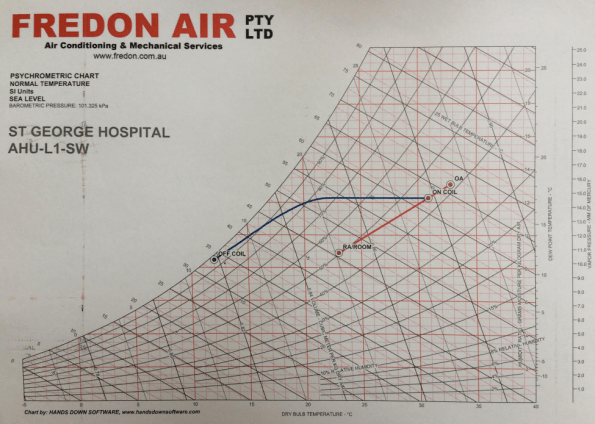
Figure 1: Psychrometric chart – not all lines are straight
- Every AHU within the hospital has been modelled separately – the understanding of these charts and the importance placed on them is clear amongst all the Fredon engineers.
Electrical and Building Management Systems. There are 3 major categories of equipment within the buildings:
- Life safety: Systems that are critical to maintaining lives in an emergency. Smoke fans, fire systems, AHUs and associated equipment for clinical areas and life support machines. The standby generator MUST be sized for 100% of all the life safety systems. In an emergency these systems are set to run to destruction. Life safety systems are covered in AS1668-1.
- Essential: These are not stipulated in AS1668, but instead are client requirements for equipment that is to be supported by standby power. Will often be connected to UPS to maintain power until the generator is running.
- Non-Essential. All equipment that is not required to be supported by standby power.
The contracts for the mechanical and electrical contractors must clearly define the division of responsibilities – usually divided either side of the Motor Control Centre (MCC). Although not applicable to the mechanical contractor, this point has been reinforced during the project between the hydraulic and electrical sub-contractors; the wiring of the Temperature Mixing Valves was a grey areas between their two contracts as no clear delineation was made, therefore they both excluded it.
With the building management system (BMS) the logic must be correct and tested prior to installation, therefore any issues on site are installation related rather than logic related. It is also far easier to resolve the logic during testing rather than using live equipment. Every item of equipment should be included and have a unique tag/number and linked to all associated equipment. It is also vital for the client to be involved in the BMS design to ensure that the required information is available on the system.
Value Engineering. The points below are key value engineering factors discussed.
- Increase ΔT (up to 12°C), many designs are conservative and only use 6°C, but modern equipment can easily sustain greater values – this saves both capital and operations costs.
- Adjust temperature envelopes to reduce the overall heating or cooling requirement; for example is it necessary to cool an office to 18°C when 20°C may be acceptable.
- Remove unnecessary plant or compromise to remove plant that will be very rarely used; e.g. there is no requirement for heating units or boilers in NSW shopping malls.
- Robust QA processes to reduce reworking.
- Simplicity of design speeds up the manufacture and installation process. It also reduces the need for meetings, reviews and workshops.
- Peer review of design to test assumptions, identify flaws and to increase simplicity.
- Overlap of design between trades; e.g. use of domestic hot water for VAV heating. In Australia domestic hot water is the scope of the hydraulic designer and subcontractor not the mechanical. However, where VAVs require only a small degree of re-heat it could be possible and more efficient to use domestic hot water lines to provide this rather than running separate mechanical hot water lines from separate boilers.
- Location of MME to reduce cabling and ductwork.
- Reduce split units and fan coil units for small or unique areas and replace them with well-designed AHUs from central plant rooms. This reduces CapEx, OpEx and maintenance burdens.
- Combine the air handling systems and the smoke exhaust systems early in the design (if possible) to reduce the cost and space of two separate systems.
- The installation of variable speed drives can generate large OpEx savings. However, VSDs do not work effectively at below 30%, if the system requires this then a bypass is needed to keep sufficient air flow through the VSD to maintain the min 30% demand.
Key lessons learnt.
Environmental knowledge and appropriate design for the conditions. Templating of design solutions does not produce efficient designs. The example given was British engineers installing heating systems into buildings during the early developments in Singapore. This is very relevant to PET designs for camps/infrastructure in different regions – this point links to the Phase 1 lectures on the same subject.
Knowledge of scope and expectations: It is important to read between the lines of a scope and make the engineering judgements to match expectation. Where the scope is not clear, then ask for further clarification or make design assumptions very clear.
Track and refine all design assumptions throughout the design process.
Start value engineering as early as possible in order to maximise the benefit and to ensure that others trades can be included.
BIM/Revit: The biggest challenge that Fredon’s engineers mentioned with BIM was the ability of their CAD users – they are computer literate and experts in CAD but they are not skilled draughtsmen, they cannot solve the engineering problems that appear, they can merely draw them.
