Archive
Conclusions on Pre-Fabrication
Pre-fabrication and off-site manufacture seem to be very popular in the UK construction industry at the moment and I have lucky to have been the lead on the largest pre-fab install on my project – a 132m long, 4m wide services culvert linking the two buildings currently being constructed.
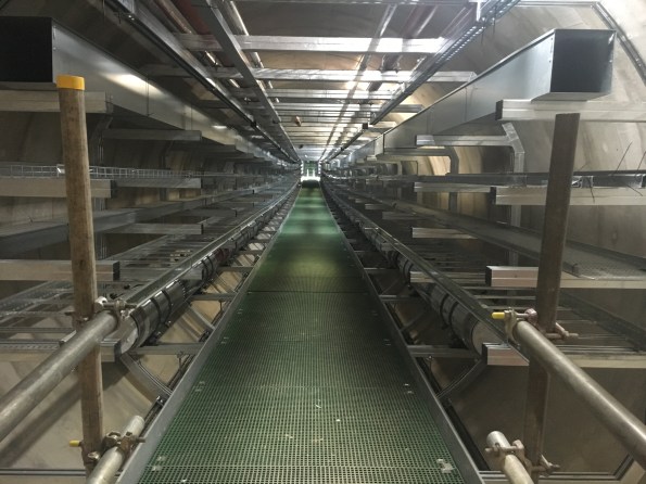
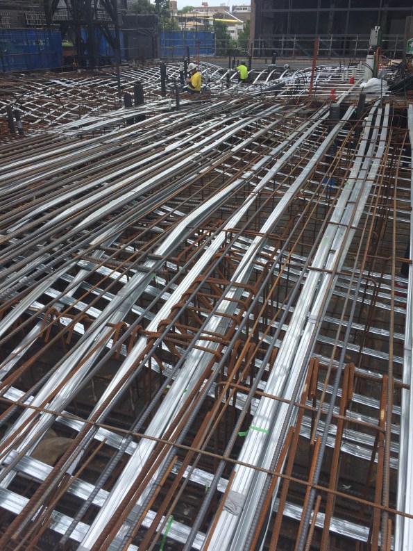
The install consists of 21, 6m long pre-fabricated modules with 12 modules installed on side of a central vertical shaft and 9 on the other. The modules carry chilled water, high-grade hot water, low-grade hot water, mains cold water, boosted cold water, sprinkler supply, HV, LV, ELV, Fire Alarms and Fibre-Optic Data. Water is transported through a series of cast pipes varying in size from 1″ to 16″ and the pipes are connected using Teekay Couples with a fixed point in the centre and expansion bellows either end of the tunnel to allowing for thermal expansion. All pipes are lagged and seated on slip rings. The cabling is fixed to a variety of containment (ladder racking and trunking) as shown in the pictures.

Background
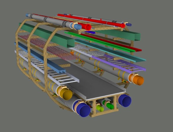
During the procurement process, a study was conducted to consider the use of prefabricated modules in the tunnel rather than traditional on-site MEP install using Unistrut bracketry. This study estimated the cost to traditionally fit out the tunnel to be £745,757. The study concluded that there could be a saving by using pre-fabricated modules manufactured off-site. Since my project uses BIM Level 2, the required module was subsequently modelled in 3D and inserted into the consolidated building model. In my opinion, BIM significantly reduces the design risk when designing complex modules or bespoke structures and for us the ability to model each module in 3D and then move it through a virtual 3D tunnel using the as -built information from a laser scan was invaluable and actually led to the height of the modules being reduced as it was clashing with a low point in the tunnel.
Once the design had been agreed and approved by the Principle Designers (BDP), it was sent to Skanska Fabrications for a mock-up to be constructed.
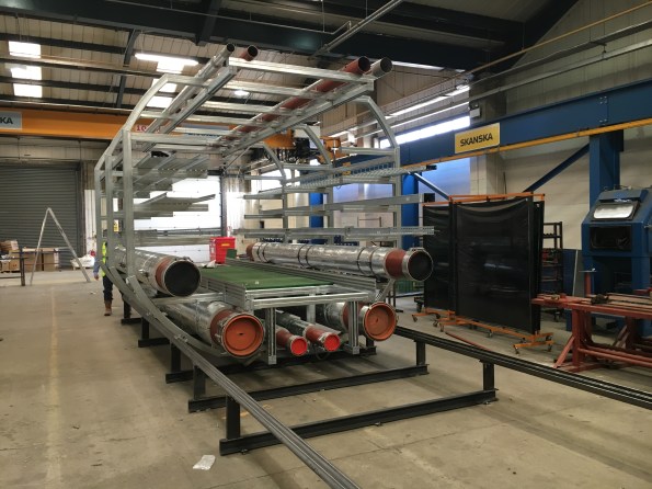
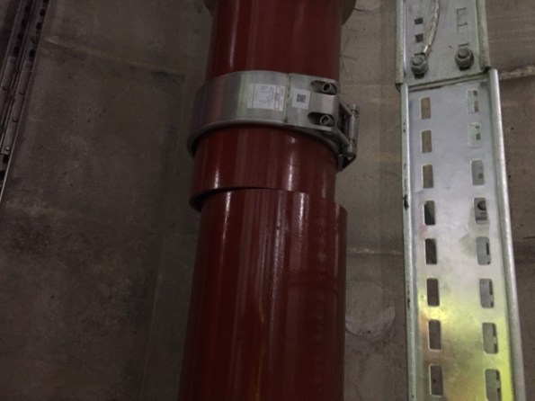
As the install lead I visited the mock-up a few times and was able to provide feedback that led to design changes that would make the install easier (one such improvement was to set back the low level Unistrut that forms the walkway to give better access to the pipe connections and Teekay couples – you can see the issue in the above photo).
Once the design had been amended and agreed upon, the package to manufacture and deliver the 21 modules was put out to tender and awarded to Balfour Beatty Engineering Services (BBES) for a sum of £460,805. Although this looks like a significant saving on the £745,757 estimated cost of traditional install, other costs need to be factored in before a true comparison can be made. In addition to the manufacture fees, the installation costs (which I tendered under my own package) totalled £86,325, the cost of realigning and connecting the pipe work was agreed at a cost of £55,493 and connecting the electrical containment has been quoted for at a cost of £11,500. This brings the total cost of manufacture and installation to £614,123 which is about 18% less than the estimation of the traditional install and has been hailed as a significant saving to Client. This cost does not take into account the additional cost of designing a more complex system and comparing the costs to an estimation is unreliable as the costs could have been over-estimated. Therefore I believe the actual saving, if indeed they was any, is actually quite small especially since a traditional install would have procured through a 2-stage competitive tendering which would likely result in a contract sum that is less than the estimation.
One of the greatest advantages of pre-fabrication is that you can remove it from the critical path in the programme and reduce the time required for on site install. By manufacturing off site you can manufacture early and store the products rather than having to wait for an area to become free or for interfacing/preparatory work to be completed. However what I have found in reality is that the time to design a pre-fabricated solution is much greater (especially if modelled in 3D using BIM) and so although you may plan to construct early, manufacturing can be delayed by the design and drawing production which is what has happened on my site. In my case, the manufacture was delayed due to a lack of drawings (this is general issue on my project!) and this in turn meant that the tunnel was left empty and ready for the modules while the modules were still be constructed meaning that there was no real time saving. Infact, if we had gone down the route of traditional install then we would have fitted out the tunnel earlier than we did.
A disadvantage of pre-fabrication is that the design needs to be agreed and fixed earlier in the programme which then creates a greater risk from design changes later on.
Installation
The tunnel modules were installed as follows:
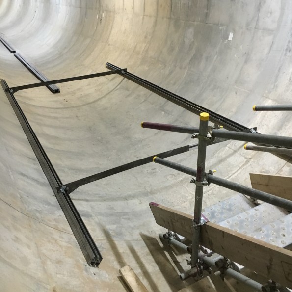
First of all a rail was installed by my sub-contractor using a jig-system:
Then the modules were dropped down the central shaft using a crane and dropped onto the rails:
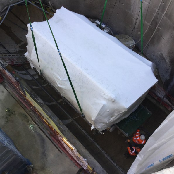
They were then dragged into position using a winch: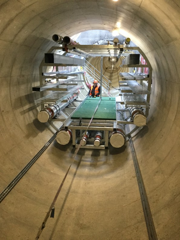
Unfortunately the installation did not go as smoothly as the above description and I had to make changes both to the method and the state in which the modules were delivered. Despite this, we installed the first module on 24 Nov 16 and the last module on 12 Jan 17. Now we have to finally align and then bolt together all of the modules before we can realign and connect the pipework and containment. Then we can also take a site measure and construct the ‘make-up section that sits in the centre of the tunnel and will fix the pipework to the tunnel wall (required for expansion).
Snagging
Inspection of the installed modules has highlighted several issues. The first is that most of the pipework is out of alignment and so will need moving in order to be connected. The mechanical sub-contractor is arguing that the amount moving and aligning required is beyond the scope of their contract and so are requesting an instruction and extra cash. It is my belief that the pipes have moved during transportation due to cyclic loads. The pipes are on slip guides and the slip guides are fixed to the modules using Unistrut channel nuts (zebedees) which rely on friction to provide a fixing. Therefore in theory all of the pipes could move if forces are applied to it outside of the design conditions. A lot of the containment is also out of alignment.
Another issue is that some of the modules do not fit together as some of the walkways and kick plates stick out too far. This makes me question how the modules were jigged at the factory – a concern I have raised with BBES. However the greatest issue with the install is that some modules are sitting noticeably higher than the others. I am still investigating the reason for this but believe it can be only one of two possibilities:
- The rail is high in places which could be due to a poor install or imperfections in the tunnel itself -several were picked up on the laser scan!
- Some modules were incorrectly constructed or mis-jigged.

Either way I need to come up with a solution and so I am looking at ways to reduce the overall module height.
Given the variety of snags and issues, I have assembled a multi-trade team using 4 sub-contractors that will go through each module and adjust every pipe, rack and section of trunking to allow all the modules to be moved as close together as possible which will minimise the gap between the pipework (maximum allowed gap is 8mm). This team will start next week which gives me a few days to work out how to lower some of the modules!
Conclusion and Recommendations
It is my experience that the conventional understanding that using pre-fabrication saves time and reduces programme risk whilst increasing costs is incorrect since on my site we have seen the exact opposite. So far on Project Laureate, using pre-fab has led to on-site delays (with knock on effects on other packages) and has cost less (18% less) than a traditional install. However, it is worth noting that this could be unique to this site due to the scale and complexity of this install or the selection of materials. Also the cost of the traditional install is reliant on an estimation which may not be accurate.
Prior to conducting this task it was my understanding and the understanding of my colleagues that the modules would arrive on site and line up perfectly, reducing the amount of time required for the on-site fit-out. Again this has not proved to be the case as none of the modules fit together without remedial works and extra time is now required for realignment. I would urge anyone running a similar task in the future to assume that any bespoke modular system being delivered to site will need a certain amount of realignment and adjustment on-site. At the very least this requirement should be priced as a provisional sum during tendering and should be included in the programme. This is particularly important for large and complex structures or systems with several variables (e.g imperfections in the final structure or multiple connections).
During the design of a module or pre-fab structure, assume that the structure it will be installed in is riddled with imperfections and plan against this to reduce the risk of delays and additional costs during the install. This could be done by adding a means of adjustment in each axis. Although this will incur additional costs, in the long it will likely save money.
When considering loads on the structure or system, also consider the temporary state such as transportation to reduce the risk of structures deforming or equipment shifting. This could lead to the requirement for bespoke bracing or supports that be will used during delivery to site.
Regularly visit and ask your sub-contractors to visit the factory during manufacture to provide feedback and to facilitate design changes that will make the install easier.
Although this package has proven to be an engineering challenge and is my greatest headache at the moment, would I use off-site manufacture again? Yes I would as I still think if done right it can offer either cost savings or time savings. However, I would implement the points above and would most likely tender it out as a design and build package to reduce the risk of delays due to an overstretched Project CAD Team. If using a Project CAD Team, I would recommend only considering the use of pre-fab for complex installs if BIM is the primary method of design.
Mark, can I count this as TMR 4?!
The Most Dangerous Dam in the world

Please forgive the blatant plagiarism. I saw these article and found it very interesting. The British Base in Iraq is 2 hrs away from this Dam. While work has been done by USACE this could involve an STRE at some point in time. The real danger point is April when the Snow Melt from Turkey hits the reservoir.
I look forward to a discussion on this topic at the Southern Hemisphere PET symposium this weekend.
The Importance of Risk Registers
I am coming to the end of my Phase 2 attachment and I have been lucky to have witnessed the majority of a contract that I planned, tendered and wrote the contract for be completed on site. However, things have not gone exactly gone to plan!
One issue with my package, which is a package to install all heavy plant in the Energy Centre and Tunnel, is that it was planned and tendered before most of the plant equipment had been procured and before the RIBA Stage 4 design had been completed. This meant that under the subsequent stage 5 design, plant positions have changed and the plant itself has generally changed in size and weight.
These changes have pushed the some of the required works out of scope and so the sub-contractor has asked for an instruction to undertake the works and of course extra cash! A saving grace is that I identified this as a risk back in May 16 and so entered it onto the package risk register with an allocated risk of £50,000. On my project, all package risk is pre-allocated by the client with a risk pot allocated for each package. Sadly, not all of the risk I identified was approved by the Client as the Client has decreed that no package risk allocation is to be greater than 5% of the package total which reduced the available risk available for scope changes due to stage 5 design changes from £50,000 to £11,000 – which is not a lot. I do not agree with this approach as some packages will always be high risk and with no means of mitigating this risk to an acceptable level. Therefore the Client is not suitably preparing for future increased costs.
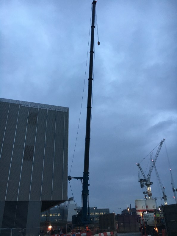
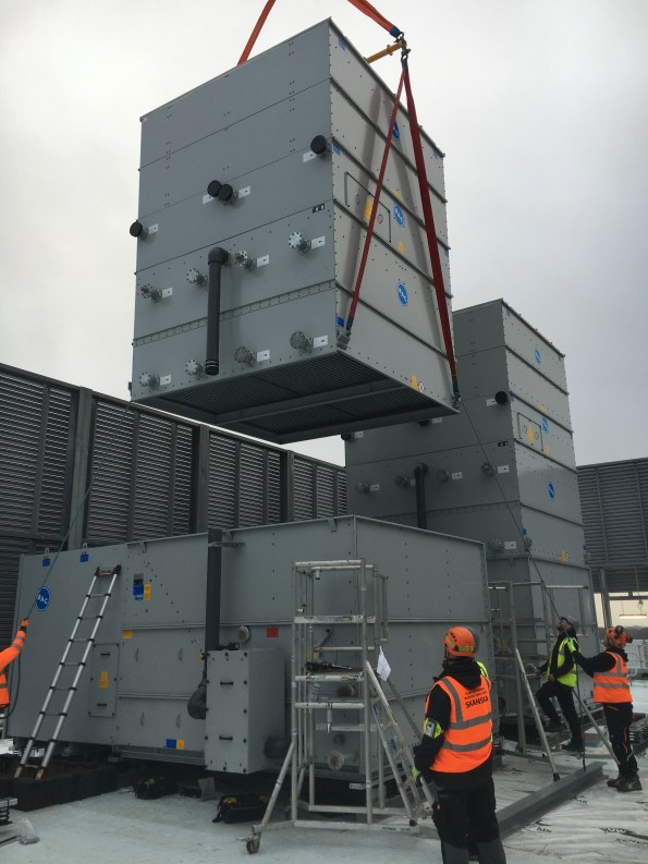
One example of these changes moving a task out of scope and requiring a change request was the installation of the five Cooling Towers on the roof of the Energy Centre. In this case both the position of the cooling towers changed just two weeks before the lift and the mass of the heaviest lift also increased from 5T to 10T as the selected supplier had a different method of installation to that used to estimate the cost of install. The combination of these changes meant that the allocated 150T crane would not be sufficient to suspend the load at the required radius and so a 500T crane was required. A 500-ton cranes requires two additional flatbeds to set and an additional set up fee of £25,000 plus an extra £3,00o for each additional day.
These additional costs were first highlighted to the Client using the Early Warning System and I submitted a change request for an additional £28,000. I had to brief this to the Client and explain why this had not been identified during tendering and eventually the Client agreed to use £11,000 from the risk pot and to publish an instruction with a cost value of £17,000. This meant that the works could go ahead but it has highlighted to me the importance of trying to confirm the scope early or at least over-estimating the scope (e.g oversize the plant) to reduce risk. That said, over-estimating in a fixed price-contracting will inevitably result in larger contract sums and so it is a balancing act to ensure an overall saving for the Client.
It has also demonstrated to me the importance of investing time into the Risk Register since if used correctly, the allocated risk pot can help get you out of a sticky situation and can be a useful source of funds if your scope proves to be insufficient. Ultimately all construction work will involve risk and it is important to both correctly and accurately identify this risk, mitigate it where possible and then allocate project funds to any residual risks. I would recommend pre-allocating funds to all residual risks so the money can be spent as soon as the risk materialises as any delays securing funds through change control will likely take time (at least a week on my site) and this in turn will likely increase overall costs and impact the all-important programme.
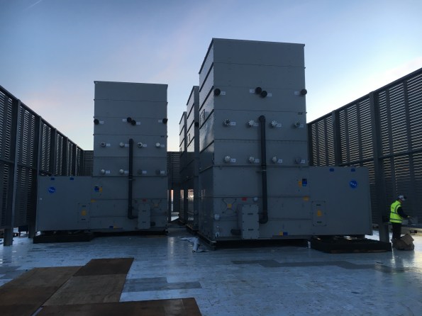
Anyway the cooling towers were successfully installed with the 500-ton crane:
But unfortunately I was not happy with the install during the QA inspection due to the misalignment of the Anti-Vibration Mounts (AVMs) and so raised this an issue with the sub-contractor.
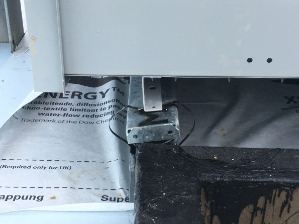
During the inspection I identified that the AVMs were incorrectly handed which was causing the AVMs to rotate. I therefore got the supplier to visit site to inspect them and they have since admitted fault and will be replacing the AVMs in March/Apr – a task that will likely fall to Will Stott to lead on during his attachment – enjoy!
Great Idea
I saw this in an email from a director while working in a design consultancy and thought what a great idea to generate work. Suggest something similar within the organizations you work for and claim it as your own idea….even earn yourself an Omega watch?
NDY Perth recently offered to update the engineering standards for the University of Western Australia (UWA) – I assume this was done at no or very little cost? This provided the university (a huge organization with enormous amounts of real estate) with up to date building/maintenance codes for which any contractor working on their site must conform to – it forms part of the initiating contract between the university and any third party contractor. In return, NDY reap the rewards of consulting on any large future projects the university carries out. Assuming UWA appoints them!! Great business methods and one in which could be applied to any large organization that maintains real estate.
Unrelated and just for fun: A friend and I were playing around with a time lapse camera this Christmas – he produced this. Pretty cool…?
Psychometric charts are not all straight lines…and other things that I have learnt about Mechanical Systems.
Summary of Design Secondment to Fredon.
Introduction
As I am not completing a typical Ph2/Ph3 attachment, I have been trying to bolster my B (Design) competencies by undertaking short design focused secondments away from Mulitplex. Fredon are the mechanical sub-contractor for the St George Hospital Project and as such design and install all the mechanical building services. In total I spent 5 days with Fredon at their design office. I benefited from this design secondment in 3 areas:
- Extending technical knowledge of services engineering.
- Reinforcement of theory and knowledge from PET course.
- Practical aspects and implications of theory.
Aim of secondment.
The aim of the secondment to Fredon was to develop a thorough understanding of the processes used for the design of mechanical building services – starting out with heat load modelling and concept design then eventually finishing with the detailed design of all the necessary elements of the system ready for installation.
Timetable.
- 5 Sept 16: Overview, heat load modelling using CAMEL.
- 6 Sept 16: Heat load modelling using CARRIER, air distribution and smoke exhaust systems.
- 12 Sept 16: Psychrometrics.
- 13 Sept 16: Cooling, balancing and valves
- 22 Sept 16: Electrical and building management. Value engineering
Key documents.
- AS1668-1: The use of ventilation and air conditioning in buildings – Fire and smoke control in multi-compartment buildings.
- AS1668-2: The use of ventilation and air conditioning in buildings – Ventilation design for indoor air contaminant control.
- AS3000: Electrical installations.
- AS4254: Ductwork for air-handling systems in buildings.
- BSIRA Rules of thumb.
- TS11: New South Wales Engineering Services and Sustainable Development Guidelines
Overview of secondment.
Design fundamentals. The key considerations before starting the mechanical design are:
- Thermal zones and environmental conditions. Australia is split into 8 thermal zones, each one with its own requirements for typical equipment and insulation. For example Tasmania requires heating, insulation and limited cooling, whilst Cairns requires significant cooling and no heating. In Australia the peak thermal loading occurs on the NW face of a building at 1500.
- Occupancy and use of building. AS1668 covers the requirements for certain building usages – for hospitals a theatre must have 20 air changes, the ED only requires 10. The occupancy of the building also changes the acceptable envelope of conditions.
- Type of building. For example in residential construction there are 5 grades of building. Grade 1 is the highest quality, Grade 5 the lowest. Clients and end users of the former will have far higher expectations of performance and quality than the latter where merely conformance with minimum AS1668 standards is required.
- Scale of the project. The scale and the life span of the project are key variables in the selection of mechanical equipment – at the smallest scale (100kw) with the shortest lifespan (25 years), a 4 pipe chiller system, with boilers for heating, will be required – the increased capital expenditure on this system will be balanced by the lower operating expenditure.
- Smoke management systems. These life critical systems are fundamental to the overall design, but due to their size and performance requirements they are also expensive. If possible, and if understood early enough in the design process then it may be possible to combine the smoke management system into the HVAC system. This point will also be covered in value engineering.
- Location of plant. This is often at the whim of the architect, but the placement of plant can have a very large effect on the operational costs of a structure. For example placing the MME close to the HV substation allows HV plant installation and the associated cost savings. Placing the plant rooms high in the structure increases the cost of the building due to the additional loads and makes replacing MME more difficult.
- Tracking and refining assumptions is critical to intelligent and accurate design.
Design software: CAMEL and CARRIER.
- During the design exercises, it was reinforced that the initial design conditions were paramount to the design’s success. Three phrases were used that I had not heard before:
- The outputs from the software are usually compared to results from previous projects and from rules of thumb calculations, Fredon do not routinely undertake hand calculations to check the results. The Fredon engineers also highlighted that both of the programmes were very conservative. CAMEL has the option to add a project safety factor; however this feature is not used as the results, by nature of the conservative model, already have a significant safety margin. In addition, the diversity used by both programmes is limited by the conservative nature of the models. As a result of this, it seems that the model is used by the senior engineers as a guideline to steer their design rather than the actual design tool.
- I completed short design exercises, based on the St George Hospital project, with both programmes. The user interface of both and the methodical process of adding the required information for the heat load calculations meant both were easier to use than HevaComp. Although the inability to import CAD drawings, and only produce 2-D results was surprisingly limiting. Once the heat loads are calculated, it is also possible to design the cooling and heating plant required for each zone/area.
- Both heat load design suites used by Fredon are 2-D only models and require the designer to input the size, shape and construction of the rooms within the building. CARRIER is a globally used design package, whilst CAMEL is the most commonly used modelling software in Australia.
- Critical design – design for the worst case.
- Comfort design – design for the average case.
- Coincident wet/dry bulb temperatures. Peak dry bulb temperatures to not occur at the same time as peak wet bulb temperatures, and vice versa. The corresponding wet bulb temperature at the peak dry bulb is the “coincident” wet bulb temperature. For example, in a design for Sydney in summer with a high air change rate it is important to use the peak wet bulb temperature and coincident dry bulb temperature as the WBT will be most critical to the design.
Air distribution systems.
The design of the air distribution system is based on a number of factors – the building’s layout and space for mechanical services; the volume of air required, number of zones and the type of load. This final factor will affect the equipment selection:
- CAV: Constant air volume. Steady loads, usually equipment loads rather than people. Small systems. E.g. clinical areas and laboratories. The temperature is controlled whilst the air volume is constant.
- VAV: Variable air volume. Changeable loads, usually from people rather than equipment. Air temperature remains constant (reheat coils can be added). High degree of control is possible. For VAV systems, it is important that the control unit is located in laminar flow so the flow can be accurately modulated – the engineers ensured the control units were preceded by 1m of straight duct. Turbulent flow over the control unit will cause it to constantly change the flow.
- VVT: Variable volume and temperature. These, more complex systems, are more expensive but provide greater control options and better responses to changing conditions.
- CRAC units: Computer room air conditioning units. The classification of the data centre (Tier 1-4) will define the spare capacity (safety factor) and redundancy of units required.
Psychrometrics/cooling/balancing. The periods spent on these subjects, as mentioned in Para 1 reinforced the theoretical lessons learnt during Phase 1 and with reference to the St George Project gave real-world examples of their application.
- The most shocking revelation was that all lines on the psychrometric chart are NOT straight – during cooling the line is horizontal until the relative humidity reaches 75% at which point condensation and therefore latent cooling begins and the line starts to curve (see below).
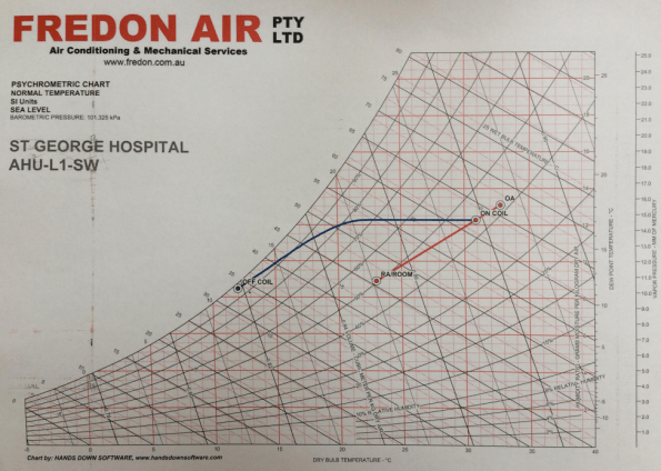
Figure 1: Psychrometric chart – not all lines are straight
- Every AHU within the hospital has been modelled separately – the understanding of these charts and the importance placed on them is clear amongst all the Fredon engineers.
Electrical and Building Management Systems. There are 3 major categories of equipment within the buildings:
- Life safety: Systems that are critical to maintaining lives in an emergency. Smoke fans, fire systems, AHUs and associated equipment for clinical areas and life support machines. The standby generator MUST be sized for 100% of all the life safety systems. In an emergency these systems are set to run to destruction. Life safety systems are covered in AS1668-1.
- Essential: These are not stipulated in AS1668, but instead are client requirements for equipment that is to be supported by standby power. Will often be connected to UPS to maintain power until the generator is running.
- Non-Essential. All equipment that is not required to be supported by standby power.
The contracts for the mechanical and electrical contractors must clearly define the division of responsibilities – usually divided either side of the Motor Control Centre (MCC). Although not applicable to the mechanical contractor, this point has been reinforced during the project between the hydraulic and electrical sub-contractors; the wiring of the Temperature Mixing Valves was a grey areas between their two contracts as no clear delineation was made, therefore they both excluded it.
With the building management system (BMS) the logic must be correct and tested prior to installation, therefore any issues on site are installation related rather than logic related. It is also far easier to resolve the logic during testing rather than using live equipment. Every item of equipment should be included and have a unique tag/number and linked to all associated equipment. It is also vital for the client to be involved in the BMS design to ensure that the required information is available on the system.
Value Engineering. The points below are key value engineering factors discussed.
- Increase ΔT (up to 12°C), many designs are conservative and only use 6°C, but modern equipment can easily sustain greater values – this saves both capital and operations costs.
- Adjust temperature envelopes to reduce the overall heating or cooling requirement; for example is it necessary to cool an office to 18°C when 20°C may be acceptable.
- Remove unnecessary plant or compromise to remove plant that will be very rarely used; e.g. there is no requirement for heating units or boilers in NSW shopping malls.
- Robust QA processes to reduce reworking.
- Simplicity of design speeds up the manufacture and installation process. It also reduces the need for meetings, reviews and workshops.
- Peer review of design to test assumptions, identify flaws and to increase simplicity.
- Overlap of design between trades; e.g. use of domestic hot water for VAV heating. In Australia domestic hot water is the scope of the hydraulic designer and subcontractor not the mechanical. However, where VAVs require only a small degree of re-heat it could be possible and more efficient to use domestic hot water lines to provide this rather than running separate mechanical hot water lines from separate boilers.
- Location of MME to reduce cabling and ductwork.
- Reduce split units and fan coil units for small or unique areas and replace them with well-designed AHUs from central plant rooms. This reduces CapEx, OpEx and maintenance burdens.
- Combine the air handling systems and the smoke exhaust systems early in the design (if possible) to reduce the cost and space of two separate systems.
- The installation of variable speed drives can generate large OpEx savings. However, VSDs do not work effectively at below 30%, if the system requires this then a bypass is needed to keep sufficient air flow through the VSD to maintain the min 30% demand.
Key lessons learnt.
Environmental knowledge and appropriate design for the conditions. Templating of design solutions does not produce efficient designs. The example given was British engineers installing heating systems into buildings during the early developments in Singapore. This is very relevant to PET designs for camps/infrastructure in different regions – this point links to the Phase 1 lectures on the same subject.
Knowledge of scope and expectations: It is important to read between the lines of a scope and make the engineering judgements to match expectation. Where the scope is not clear, then ask for further clarification or make design assumptions very clear.
Track and refine all design assumptions throughout the design process.
Start value engineering as early as possible in order to maximise the benefit and to ensure that others trades can be included.
BIM/Revit: The biggest challenge that Fredon’s engineers mentioned with BIM was the ability of their CAD users – they are computer literate and experts in CAD but they are not skilled draughtsmen, they cannot solve the engineering problems that appear, they can merely draw them.
Phase 3 – Week 1
At the start of this week I began my Phase 3 attachment with Ramboll in Birmingham. I am working in the Buildings department, currently tasked with an Energy from Waste (EfW) plant in Gloucestershire, this is a power plant that burns non-recyclable waste to produce power (E&Ms can tell you more).
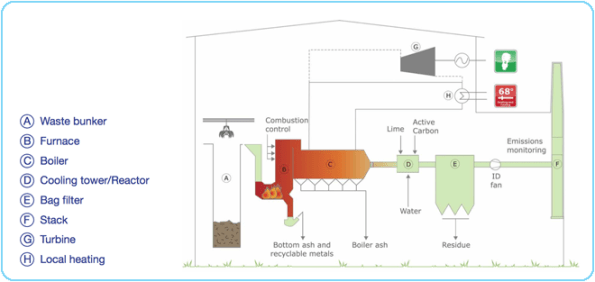
The EfW plant is basically a series of huge steel structures with smaller concrete structures inside them. The loads from the mechanical plant in here pose the biggest issues to the designers, as well as another engineers designing the mechanical systems, they are also responsible for the steel work that supports this. Ramboll are essentially responsible for the housing structure and foundations.
In my first week I have been tasked with looking at the Boiler hall structure. An RC box that houses the turbines and boilers (big loads). The client initially issued loads on the agreement they would not increase by more than 10%. These have now more than doubled and I needed to assess whether the beams and columns were still sufficient at current sizes (increase in steel was presumed).
The critical beam was already 2m deep spanning 13.58m and the column this sits on is 14.75m tall (750mmx750mm). After my week of assessments (by hand) the beam has increased to 2.5m deep and the column is just about suitable. I have also now designed a new roof slab which sits on top of the Boiler hall with some water tanks and other loads.
I think I have just about got through the other engineers watching me struggle with hand calcs and lots of rubbing out, whilst everyone else bashes away at their computers. I will add some photos from the computer model when I have worked out how to Print Screen!
Site Inspection – in at the 1.4m deep end…
Anybody interested in what a site inspection of 1400mm deep, 5.5m cantilevering transfer beam designed to support 18 storeys looks like…
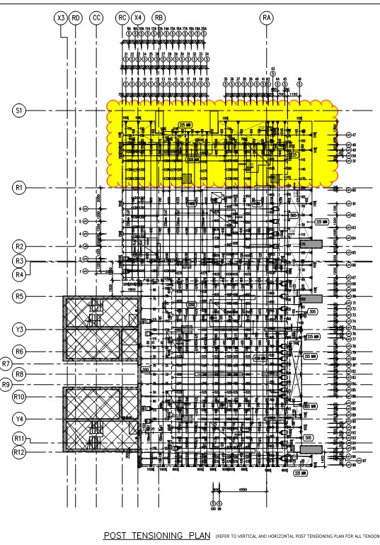
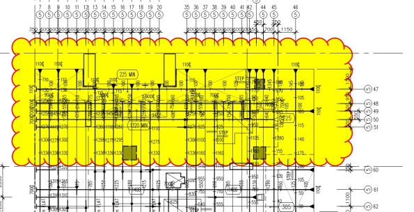
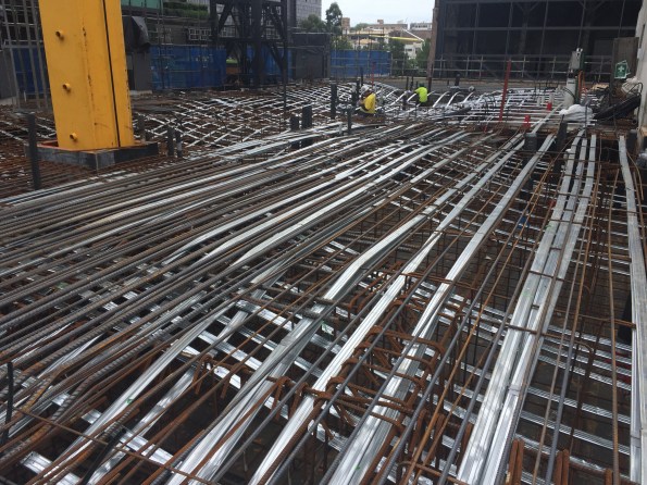
The PT is made up of 15.2mm diameter strands @ 300 centres. The cantilever supports 18 storeys with only 20mm deflection!
The construction of this was not simple. PT design is not in the structural engineer’s package, it is in the PT sub-contractor’s. Their original design saw almost half the amount of PT shown in the photo but and deflection of 38mm. By the time the design consultancy had highlighted the need to restrict deflection to 20mm, the PT had been assembled as per the original design. You can imagine the look on the contractor’s face when they were told more PT was needed. Due to congestion, the additional PT could not be added in a side-by-side arrangement, but by way of a second layer in the vertical plane. The contractor was not happy.
Steel Connection Failure
I remember with joy the moments in the Phase 1 lectures when the Lecturers outline various design approaches (let’s call them easy, complicated and devilish), and then tell us to draw a line through complicated and devilish, “you’re a fool if you choose those options, we’ll focus on the simple option for this tutorial”. Brilliant news.
Looking back through my Steel connection notes this is exactly what I’ve done and all of my Ex Steel joints were designed as simple connections (i.e not moment connections). However, it’s not always possible to draw a line through the difficult options.
One of the projects I’m working on over the next few weeks is the back analysis of steel connections in a building which has experienced a failure during use (a loud bang at night as one of the connections failed). I’ve still got a lot of work to do but below are my initial musings from SCI P207/95.

Figure 1 – Failure of B33 to C13 connection
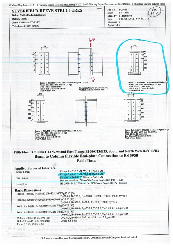
Figure 2 – Steelwork contractor calculation output
The frame was designed by my consultancy and a steelwork contractor designed the connections. The design of the connections was carried out using Masterkey software to BS 5950. The BS states that when the design is handed from a Structural Engineer to a Steelwork Contractor the contract documents and design drawings must adequately define the design requirement for the connections. Further guidance within the National Structural Steelwork Specification for Building Construction states this information should include:
- Design concept
- Member schedule and drawings
- Design standard to be used – in this case BS 5950
- Forces, moments and combinations at each connection – some raking/angled beams also have an axial force to consider.
- Factored or unfactored loads used
- Restrictions on joint details
My task is to back analyse the connections designed by the Steelwork Contractor, using the same software in order to check their connections for revised actions. The reason the actions have been revised is because regardless of whether the connections were designed as simple or moment connections (the two simpler design approaches), the reality is that there will be a degree of deformation at the connection, therefore the joint will really be acting as semi rigid with some degree of rotational deformation. If the connections is partially deforming then part of the moment will be transferred into the adjacent beam, in the case of a double beam to column connection, and part into the column.

Figure 3 – Classification of moment connections as per SCI P207/95
Initial investigations have shown that some of the “simple” connections may be too robust to act as a simple connection, and will in reality transfer some of the moment through the connection. Take note McClure – you shouldn’t always go big early.
Sustainable Engineering and Midnight Lux Levels
Happy new year to all! An update from Gatwick…
Sustainable Engineering
In order to bolster my E3 UK Spec competency of proving sustainable engineering, I’ve managed to get involved with the in-house Environment and Sustainability team. I’ve now got responsibility for an embodied carbon survey to be conducted on the newly finished Pier 1 (see http://www.dailymail.co.uk/travel/travel_news/article-3640991/Gatwick-unveils-186m-state-art-terminal-link-fascinating-time-lapse-video-showing-construction-hi-tech-new-baggage-system.html for a rather good time lapse video – particularly of the baggage system!).
The survey is aimed at quantifying the amount of carbon emitted to atmosphere during the manufacture, transport and construction of the building and it’s materials per m2. This will give a measured baseline of Gatwick’s current sustainable construction performance and try to fill the void between strategic aims of ‘constructing more sustainably’ and the on the ground reality of how well projects are delivering to this.
Broadly, materials such as steel tend to have much higher embodied carbon due to energy intensive manufacturing process. Materials such as timber have much lower embodied carbon as less energy is required to produce it.
The aerial shot below gives an overview of the existing understanding of the Gatwick site’s embodied Carbon, which is currently quite rudimentary and not much more than a wet finger estimate. Green indicates low embodied Carbon, red indicates high. Pier 1 is the red block to the right hand side of the site view.
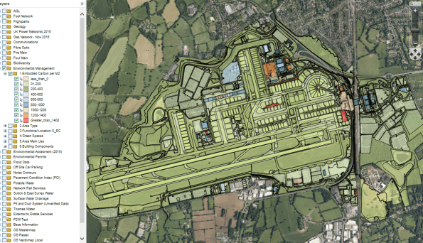
Once the detailed Pier 1 survey is complete, I aim to suggest suitable recommendations into Gatwick construction material standards to reduce embodied carbon where possible.
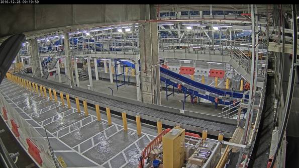
Night time lighting testing.
The first project of the baggage programme is now in the testing and commissioning phase (see progress photo below). For my electrical package, this involved dead and live testing of final circuits, testing of the lighting controls and testing that the specified lighting lux levels have been met.
Emergency lighting testing must be conducted outside of working hours to allow the bag hall regular lighting to be switched off, thus I joined the contractor to conduct the lighting and emergency lighting test in a window between 2330hrs and 0230hrs with lux meter in hand to conduct the tests. In the photo below (yes, that is my hairy arm) we are testing that the electrical distribution board receives the minimum of 300lux on vertical plane under normal lighting conditions prior to testing that it meets 15 lux under emergency lighting conditions (and after 3hrs drain of the battery).

