That’s not a crack this is a crack!
![IMG_6764[1]](https://pewpetblog.com/wp-content/uploads/2017/03/img_67641.jpg?w=595)
I thought BCT had problems! My boss and I were called in to investigate a crack at the Fortitude Valley Site. They are having some problems with their consultants. They have recently installed a crane and they thought it might have caused this cracking. It hadn’t what had caused the cracking was a construction joint that hadn’t been correctly designed. The connection had failed and there was evidence of shear cracks across the slab where the load had tried to redistribute. There are 20 floors of load on this slab!

Johnny Age 5 sketch
![IMG_6774[1].JPG](https://pewpetblog.com/wp-content/uploads/2017/03/img_67741.jpg?w=595)
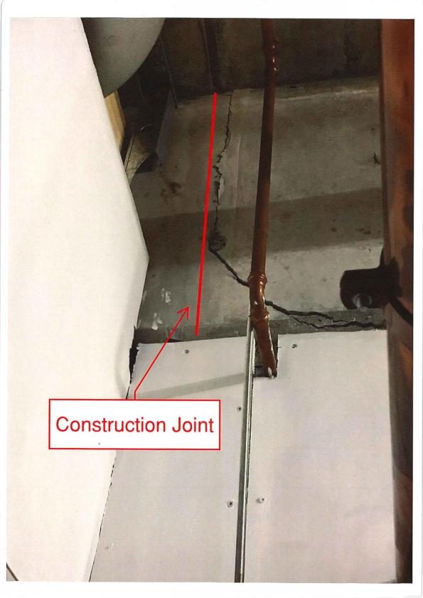
This shear crack doesn’t look much but it shows that the transfer slab is in distress. Note the angle of the crack. Construction joint is above pipe
- Lack of specific construction joint for the transfer slab.
- The key of the construction joint was too close to the bottom of the slab. All of the vertical load was being transferred into the key detail at the bottom of the slab that then sheared off.
- In sufficient shear reinforcement.
- Construction joint located near an area of high shear.
- lack of oversight by structural engineers in Melbourne.
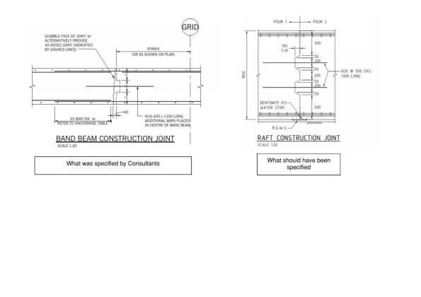
The Bad (what was detailed left) and good (detail from another site right). Note the key detail on the right and roughed finish

The offending construction joint before the pour. Note – no shear reinforcement and the key is close to the bottom of transfer slab!
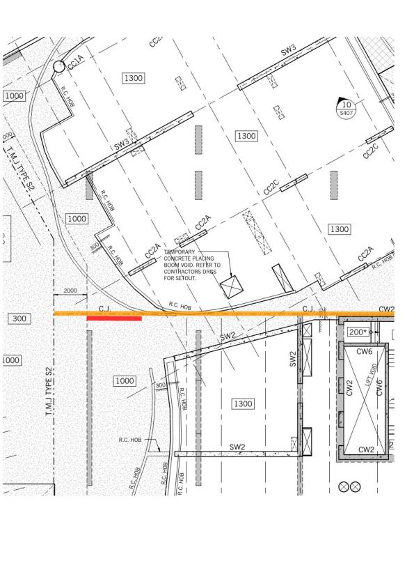
Plan view of the site (red is area of cracking). CC2A are columns that terminate at the transfer slab.

Doug, I bet you were highly disappointed with this after being told you were going to see a crack in the fortitude valley!
I might be wrong here but would the cracking have anything to do with poor concrete connection/bond at the joint? The face of the construction joint looks very smooth in the pre-pour photo. I believe that concrete is usually blasted with a pressure washer before a pour in order to expose the aggregate and get a good bond. This might be an additional reason for the failure.
Good one – even funnier when you consider Fortitude Valley is the red light district! You’re on to something Fred. It should have a roughed finish it’s one of the many things wrong with this joint
Of course if you model the shear resistance as a strut and tie model you require the concrete to work in compression only rather than using the design resistance capacity in shear Vrdc. In the latter case the absence of steel links is the issue rather than the concrete interface but, in the absence of the steel, reliance is placed on the concrete and the resulting failure would be expected. I’m struggling a little with Jonny’s sketch because I’m unclear what the actual model is for span directions, applied actions and load paths but I think I can jut about work it out. I’m also not sure that the ‘good’ detail is that much better designed albeit that it may have a greater shear resistance. Most interesting now is how are you going to analyse what is there and what is the design solution? Sun headline “British Army officer works to resolve inadequate member problem in Australian red light district”
Unfortunately Richard I didn’t have the full set of drawings (why would I) this seemed to be done with sketches. Reference good detail. It came from my boss Matt Irwin (Senior Principal)and is indicative only and highlights a better key detail. It was used in a hydrostatic slab. But I will let him know you don’t like his work.
Btw Answer prop both sides of CJ 32 mm stress bar drilled through the slab at 350 centres with 50 mm plate. Stress bar until deflection has reduced.
Doug, I like the blog topic and content and wouldn’t want full drawing sets anyway. I just wondered how this band beam was working within the structure. We might discuss pre CPR, although you have more than enough material for that already. Matt’s detail makes perfect sense for a shear key on a ground bearing slab. This is not the same situation. The solution is interesting because I think you have provided additional tensile steel in the form of a thick plate which has been fixed in place by through fixing vertical steel and tensioning. Has the existence of shear steel in general been looked at and does this solution address the design flaw or just the visible problem?
We are looking at the other slabs now and have established a traffic light system to prioritise. The lack of shear ties is concerning and when we saw the pre-pour photo there was a oh shit moment. This is actually a transfer slab and supports one of the columns of the tower almost slap bang between the 4 supports. Well three supports because it is cantilevering here because this has failed. The solution covers the structural problem but it will be anything but aesthetic. We will have to hide it under a planter. God knows what the other CJs look like. If we can find some bloody drawings.