Archive
Bouncy Bridge
Good news! If you are a person who takes to train to Luton airport and have to deal with the shuttle bus to the airport terminal, worry no more. The owners of the airport have realised that the fact you need to take a bus to the terminal is putting off people travelling to their lovely airport and are doing something about it.
Arup have been working on the design for an automatic shuttle system (MPT – Mass Public Transit); think North to South Terminal at Gatwick Airport. Which will whisk you from the National rail platform up an escalator to a footbridge and into the Airport terminal in 4 minutes.
You may have seen an article in the press/ NCE magazine.
https://www.newcivilengineer.com/latest/115m-luton-airport-rail-link-tender-out/10017758.article
https://www.newcivilengineer.com/latest/details-revealed-for-luton-gateway-bridge/10017973.article
Network Rail Footbridge
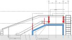
As part of this project, over the last 3 weeks I have been working on the design of a steel footbridge structure which will span over the rail tracks at Luton Parkway Station. The bridge will connect into two lifts (which are self-supporting) and five escalators supported by bridge superstructure.


The bridge itself is a continuous steel vierendeel truss (I had to look into vierendeel trusses to realise that a vierendeel truss isn’t actually a truss, but this point is probably for another blog). The bridge is supported on three pairs of portal frames that sit on the station platform supported by piled foundations. All sections are welded rectangular steel sections. The shape of the portal frame is unconventional and is driven by the architects to maintain as much clear space under the bridge to increase sightlines. It is this shape which is starting to cause problems.
There a number of loads and combinations acting on the portal frames however the main variable loads are from the bridge and the escalators. Which act to destabilise the portal frame. Its easy to realise that the shape isnt the best for a portal frame. As the frame is loaded at mid-span the horizontal members want to straighten an overturning moment is generated to topple over the tallest column.
-
- Main Variable Actions on the Portal Frame
-
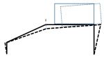
- Deflection of the Portal Frame
3D modelling
I have generated a model of the bridge in GSA (design programme written by Arup) to compare against my hand calcs and to model the 3D element of the structure. the age old problem of whether to model the frame with pin supports or moment connections raised its ugly head.
Modelled with pin supports deflections at the top of the escalator are about 40mm. Although no one can tell me what the allowable deflection for an escalator is I am assuming this this is too high. Does anyone have any experience with deflection in escalators? If I fix the column supports I can reduce the deflection to what I think is a more manageable 15mm however this generates a 2MNm moment which needs to be restrained. Meanwhile, I am looking to shorten the span from 18m though this requires negotiation with the architects.
Dynamic modelling
Arup’s experience with ‘bouncy bridges’ is quite developed following from history that people are happy to talk about. Arup are responsible for the millennium bridge fiasco though I am reliably informed by tony that the engineer responsible no longer work with Arup and works at Tony’s placement.
The dynamic response of bridges has been an interesting learning curve. Eurocode 1991-1-4 states that if the wind response frequency is above 1Hz then a dynamic check need to be conducted anyway. I have conducted a dynamic analysis of 10 modes which only considers the dead and superimposed dead loads. Unfortunately most modes have frequency between 2Hz and 7.5Hz, which puts it at risk of user induced oscillations.
These are videos of two of the dynamic modes of failure. In both the deflections are severely exaggerated but they are interesting and show the movement. You can also see that the deflection is largely as a result of the portal frame. Hopefully the videos work.
The second largest movement is due to the articulation of the bridge. The bridge is fixed to the portal frame at the centre on a pin bearing which means that all lateral forces are resisted in a rather small portal frame (2.75m wide) acting in the minor axis of the section.
Next Step
The design is still developing so there is still further to go. I initially left out the floor plate from the model as I wanted to be conservative. However by including it should stiffen up the lateral movement. I have also arranged a meeting with the architects to see how we can reduce the span or even the angle of the portal frame.
Watch this space.
Airport East; Demonstrating the Ground is a Risk.
Background
Sydney Kingsford Smith Airport and Port Botany are two of Australia’s most important international gateways. The roads around the airport and Port Botany are becoming increasingly congested due to the rising numbers of passenger and freight vehicles. The Airport East Precinct project will support the development of the West Connex motorway, which will improve access between this area and Western Sydney.
Project Overview
The Contract is for road and rail bridge construction on General Holmes Drive, Botany Road, Wentworth Avenue, Joyce Drive and Mill Pond Road in the east precinct of Kingsford Smith Airport at Mascot.
As site engineer I am currently overseeing elements of the installation of a new two span reinforced concrete bridge linking the new Wentworth Avenue underpass to General Holmes Drive (GHD) shown in figure 1 and tendering for the precast bridge planks.
The site is heavily congested and restricted, an active freight railway line dissects the centre. A sewer, high pressure gas line, and canal also create obstacles which have load limits imposed on them; therefore manoeuvring machinery is posing to be a real headache. There is also a vertical limit of an obstacle limitation surface; this defines the airspace surrounding Sydney Airport that must be protected from obstacles so aircraft are free to descend without interference landing.
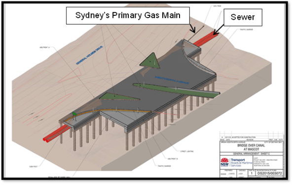
Figure 1 – Bridge Linking GHD to Wentworth Avenue Underpass
Vibration Management
The east runway is undergoing maintenance from 24 March 17 – 3 April 17 which allows the tall piling rigs to be set up. I have noticed rotary aircraft using the eastern side of the runway so have suggested that red warning lights (complying with Civil Aviation Authority Standards) are attached to the top of each of the piling rigs and included in the activity method statements.
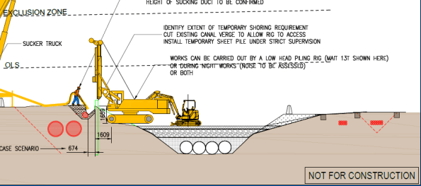
Figure 2 – Non-destructive Excavation & Sheet Piling Stage
A sheet pile wall will be installed adjacent to the primary gas main that will serve two functions (figure 2);
a. Retain the existing ground profile and allow for backfill around the gas main to eliminate any potential settlement or subsidence through piling and bridge substructure works.
b. To provide robust sacrificial formwork for the capping beam / pile cap.
Prior to installation of the sheet pile, non-destructive excavation was used to determine the exact location of the gas main and extent of stabilised sand backfill around the services (figure 3).
During the sheet piling, vibration monitors have been installed along the sewer and gas main to record vibrations which may occur. Limits of vibrations which cannot be exceeded for the gas main are 20 mm/s and 5 mm/s for the sewer. If the vibration limits do exceed this, a silent piling rig will be utilised. I have questioned these figures as I was asked to research ground borne vibration on buildings within the area and DIN 4150-3 limits peak particle velocity to 3 mm/s on sensitive buildings.
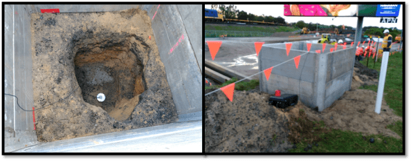
Figure 3 – Vibration Monitoring of Gas Main
The silent piler uses the ‘press in’ method, grasping the previously installed piles and establishing a reaction force from the negative skin friction and interlock resistance of the previously installed piles. Since the piles are pressed in this method does not cause any damage to the environment including neighbouring structures, assets or residents through noise and vibration.
Contamination
The project site is contaminated with poly-fluoroalkyl substances, known as PFAs. These are a group of manufactured chemicals contained in firefighting foam, they are added to improve the foams ability to smother fires. Therefore the likely source is Sydney Airport, the drainage for the airport runs through the site. The pathway and transfer of the PFAs is via the natural ground water flow through the site, and the possible receptors are workers and local residents as excavation occurs. They are a carcinogenic but are not found in high enough concentrations in the vicinity of the site to cause harm to workers.
Continuous flight augering (CFA) piling is being used due to the poor ground conditions and lack of cohesiveness of the loose, brown/grey fine to medium SAND. This method of piling stops the excavation collapsing due the concrete being pumped in as the helicoidal auger is extracted to give positive pressure to the excavation walls.
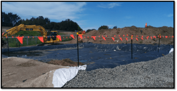
Figure 4 – PVC Barrier Layer for Spoil Heap to Limit Contamination
Excavated spoil is going to be placed in spoil heaps as to not contaminate the top soil. The PVC sheet is used as a separator and for the site to be compliant with the Australian Environmental Agency requirements. After looking at the design borehole (figure 5) for the site, I noticed the differing concentrations in PFA’s across the site. I have suggested that separate spoil heaps are created for different areas of excavation as to not waste money in disposal of contaminated waste which is has a different concentration of PFAs.
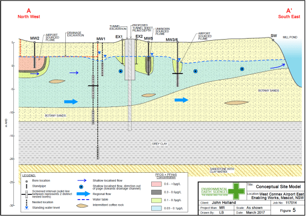
Figure 5 – Design Borehole for Site
CFA Piling Issues
As stated earlier the ground conditions are dictating that CFA piling is used. There have been some difficulties though when driving the cage into the poured concrete. Even though the water table is -3m AOD the loose, brown/grey fine to medium SAND is absorbing the moisture content of the concrete causing the concrete to cure quicker than expected. The concrete used has 240mm slump and aggregate size of 10mm (primarily to fit down the CFA tube). To overcome the issue 2m of concrete is being poured then immediately drilled out, lining the excavation with a layer of concrete to mitigate the loss in moisture content. Currently an excavator bucket is being used to push the cage into the concrete, but vibration of the cage is also being looked into. Thoughts on the use of a plasticiser?
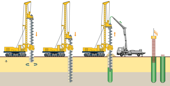
Figure 6 – CFA Piling Process
