Bouncy Bridge
Good news! If you are a person who takes to train to Luton airport and have to deal with the shuttle bus to the airport terminal, worry no more. The owners of the airport have realised that the fact you need to take a bus to the terminal is putting off people travelling to their lovely airport and are doing something about it.
Arup have been working on the design for an automatic shuttle system (MPT – Mass Public Transit); think North to South Terminal at Gatwick Airport. Which will whisk you from the National rail platform up an escalator to a footbridge and into the Airport terminal in 4 minutes.
You may have seen an article in the press/ NCE magazine.
https://www.newcivilengineer.com/latest/115m-luton-airport-rail-link-tender-out/10017758.article
https://www.newcivilengineer.com/latest/details-revealed-for-luton-gateway-bridge/10017973.article
Network Rail Footbridge
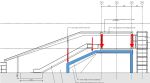
As part of this project, over the last 3 weeks I have been working on the design of a steel footbridge structure which will span over the rail tracks at Luton Parkway Station. The bridge will connect into two lifts (which are self-supporting) and five escalators supported by bridge superstructure.


The bridge itself is a continuous steel vierendeel truss (I had to look into vierendeel trusses to realise that a vierendeel truss isn’t actually a truss, but this point is probably for another blog). The bridge is supported on three pairs of portal frames that sit on the station platform supported by piled foundations. All sections are welded rectangular steel sections. The shape of the portal frame is unconventional and is driven by the architects to maintain as much clear space under the bridge to increase sightlines. It is this shape which is starting to cause problems.
There a number of loads and combinations acting on the portal frames however the main variable loads are from the bridge and the escalators. Which act to destabilise the portal frame. Its easy to realise that the shape isnt the best for a portal frame. As the frame is loaded at mid-span the horizontal members want to straighten an overturning moment is generated to topple over the tallest column.
-
- Main Variable Actions on the Portal Frame
-
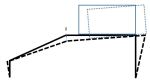
- Deflection of the Portal Frame
3D modelling
I have generated a model of the bridge in GSA (design programme written by Arup) to compare against my hand calcs and to model the 3D element of the structure. the age old problem of whether to model the frame with pin supports or moment connections raised its ugly head.
Modelled with pin supports deflections at the top of the escalator are about 40mm. Although no one can tell me what the allowable deflection for an escalator is I am assuming this this is too high. Does anyone have any experience with deflection in escalators? If I fix the column supports I can reduce the deflection to what I think is a more manageable 15mm however this generates a 2MNm moment which needs to be restrained. Meanwhile, I am looking to shorten the span from 18m though this requires negotiation with the architects.
Dynamic modelling
Arup’s experience with ‘bouncy bridges’ is quite developed following from history that people are happy to talk about. Arup are responsible for the millennium bridge fiasco though I am reliably informed by tony that the engineer responsible no longer work with Arup and works at Tony’s placement.
The dynamic response of bridges has been an interesting learning curve. Eurocode 1991-1-4 states that if the wind response frequency is above 1Hz then a dynamic check need to be conducted anyway. I have conducted a dynamic analysis of 10 modes which only considers the dead and superimposed dead loads. Unfortunately most modes have frequency between 2Hz and 7.5Hz, which puts it at risk of user induced oscillations.
These are videos of two of the dynamic modes of failure. In both the deflections are severely exaggerated but they are interesting and show the movement. You can also see that the deflection is largely as a result of the portal frame. Hopefully the videos work.
The second largest movement is due to the articulation of the bridge. The bridge is fixed to the portal frame at the centre on a pin bearing which means that all lateral forces are resisted in a rather small portal frame (2.75m wide) acting in the minor axis of the section.
Next Step
The design is still developing so there is still further to go. I initially left out the floor plate from the model as I wanted to be conservative. However by including it should stiffen up the lateral movement. I have also arranged a meeting with the architects to see how we can reduce the span or even the angle of the portal frame.
Watch this space.
