Archive
One Nine Elms – How not to design a structure
So, hello everybody. I hope everyone is settling in well and the Australia lot are not too sunburnt. In order to not bore everyone by just regurgitating AER 1, I intend to give you a brief overview of my site and then discuss the main issue with the project.
HEALTH WARNING – it’s a long one, sorry.
One Nine Elms – Multiplex
I am currently a site engineer for Multiplex on the One Nine Elms project. Multiplex have been brought in by Wanda (the client) after a number of contractors had walked away, being unable to agree on price and the project was showing little progress being almost a year behind schedule. The current contractual arrangements are slightly confusing but in essence everyone is currently under contract directly to Wanda. Second London Wall (Employers Agent) are the clients advisors and Multiplex under a Construction Management contract, but with not direct control over the sub contractors. All this makes for a confusing and rather inefficient site however, Multiplex will be moving to a Design and Build contact in June with the client becoming Second London Wall. I suspect this will be a future blog or TMR once it becomes a little clearer.
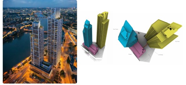
Fig. 1 Architects Impression (Left) and Superstructure 3D (Right) – notice the lack of St George Wharf completed in 2014
The site is the redevelopment of the Market towers, two 23 storey RC towers completed in 1975 and demolished by McGees in April 2015. Piling and groundworks began on site during the demolition and is not likely to be complete until the early 2018 which I will elaborate on below.
Superstructure
The superstructure consists of two high rise buildings referred to as the City Tower (yellow) and the River Tower (blue), the towers are linked at the first floor with a link bridge via a podium (purple). The City Tower is 56 storeys assigned for residential occupation, with the River Tower being 42 storeys with the upper levels being for residential occupation and the lower levels assigned as a hotel along with the podium. The structural concept for both towers is typically post tensioned reinforced concrete solid slabs supported by composite concrete encased steel columns and a centrally located reinforced concrete core. The reinforced concrete core along with its buttresses provide the lateral stability to the building, floor plates act as diaphrams restraining columns and transfer lateral loads to the core.
Substructure
There are two basement levels across the whole site with a third level between the two towers. A 1750mm combined sewer runs through the middle of the site which splits the substructure in two. Groundwater cut off is achieved by two 800mm diaphragm walls boxes either side of the sewer which have a toe depth in the London Clay. The foundations supporting the Superstructure consist of 256 compression and tension bored piles acting in conjunction with the raft at B2 level. These piles vary in diameter ranging between 1800mm and 900mm with the toe in the Thanet Sands. Due to the proposed construction sequence some of the piles contain plunge columns.
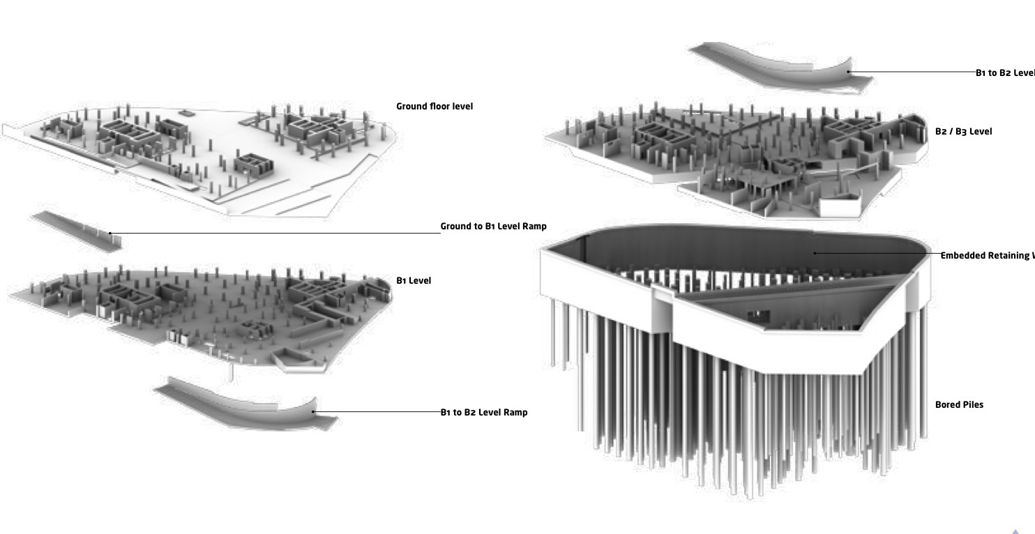
Fig 2 Diagram of substructure
Ground Conditions
The ground below the site is typical of London and consists of Made Ground (depths between 1.1m – 4.90m), Alluvium (depths between 4.5m – 9.5m), Kempton Park Gravel (depths between 7.5m – 23.0m), London Clay (depths between 22.0m – 31.5m), Lambeth Group (depths between 10.5m – 16.2m), Thanet Sand (depth between 9.2m and 13.0m) above the Newhaven Chalk Formation. Groundwater is between 3.7m and 6.4m deep and is known to fluctuate, with the level of the Thames. Fig 3 below shows the Lithology along the route of the sewer, there is a scour Pingo feature in the East of the site and it can be clearly seen on the right below.
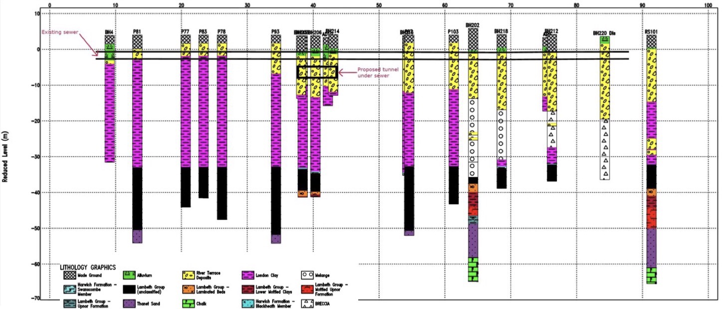
Fig 3. Lithology along the length of the sewer
Construction Sequence
The original squence and design was for top down whilst constructing the two tower cores on a number of plunge columns simultaneously, in theory reducing the project duration. However due to issues with the sewer which I will outline below the sequence has gone to pot and now looks like bottom up around the River Tower and top down around the City Tower.
Sewer Issue
As mentioned above, the site sits directly over an existing Victorian masonry combined sewer. The Market Tower (old building) basement structure spanned over the sewer and was supported on piles either side with a 1.3m to 1.5m exclusion. Where superstructure columns landed within the exclusion zone a 2m deep slab transferred the load to piles either side. The same solution has been proposed for the new building – First error!
The option to construct a new sewer around the perimeter of the site was tabled at a cost of around £2 million, this was rejected by the CEO of Wanda. The reason cannot have been for cost. The 150m of extra diaphragm wall, two 2m deep steel transfer beams, fabricated out of 200mm thick plate which take down a main load path over the sewer and the 1000 tonne crane to lift them in will cost significantly more. Mental!
Having made the decision not to construct a new sewer, the next worst possible decision would be to let the achitects put the taller of the two towers where the scour feature is. Hence requiring a greater number of larger piles to carry the larger loads in more difficult ground, which raises issues of conflicting with existing piles….. You guessed it. The core of the 56 Storey City Tower is smack bang over the sewer and in the worst ground. Not only this but due to load exclusion zone the two huge transfer beams mentioned above are now required. Mental 2!
So you would think with everything mentioned above, a detailed internal monitoring system of the sewer would be wise to compare displacements to expected values….. Nope. Wanda decided it didn’t want to waste money installing a detailed monitoring system during the demolition (against the advice of pretty much everyone involved in the project), instead opting for an Invar rod and tube system on the crown of the sewer. These are cheap but have numerous disadvantages, such as not being very accurate being suceptible to temperature change and being surface laid are easily tracked over and disturbed by plant.
Analysis was conducted to estimate the sewer movement during demolition (heave due to a reduction in effective stress in the clay) and settlement during the construction of the D Wall and permanent structure. This analysis predicted vertical sewer deflections of +27mm during demolition, +63mm during excavation and on completion of the superstructure of +28mm (que a JM rant on accuracies in geotechnics). An interesting point here is that the new structure makes a better job of spreading the load across the footprint of the site, hence the heave remember JMs voids ratio v effective stress.
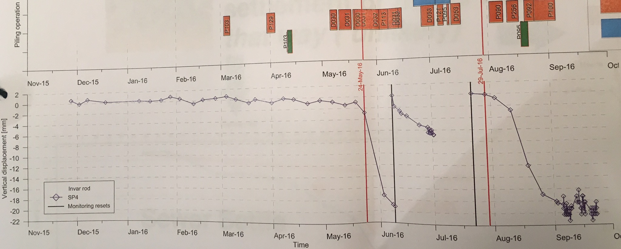
Fig 4 weekly Invar Rod monitoring results overlaid with activity, piling (green), Coring (orange)
As can be seen in Fig 4 above, the coring of existing piles for construction of the D wall seems to suggest about 50mm of settlement, combined with 200mm of settlement known to have occurred before 2013. This puts the sewer way beyond the allowable strain stated by Thames Water (TW). The large jumps and the rod resets (black lines), raise the question of the reliability of the results but if this is all you have then it has to be trusted.
As a result of this settlement TW have imposed a 7.5m load exclusion zone either side of the sewer, until its integrity can be guaranteed . This effectively makes the completion of the piling impossible and blows the programme to bits. The current solution is to line the sewer with a steel liner, this maybe jacked down the sewer or lifted into place by cutting out the crown. These are subject to TW approval of the method. This work will take 30 – 40 weeks which is a direct delay to the project, as the effected areas are on the critical path and at an unknown cost (this will be a subject of a future blog). On top of this the D wall and key piles for transfer beams can not be done until after the sewer remediation. The clamshell rig leaves site for another job next weekend, leaving an incomplete GW cut off and a fairly large bentonite farm in the only area where work can continue. This is a pretty big issue, these rigs normally require a big lead time, booking for 9 months or more and have a significant establishment cost. Due to the depth required and then associate problems on achieving interlock due to tolerances, a secant wall solution may not be possible. The resultant of this is Wanda considering purchasing their own clamshell rig at a cost of £1.2million and MPX under considerable pressure to demonstrate to the client that are worth there margins.
Sorry for the long one, I’ve probably glossed over some vital information so fire away.
