Archive
100 Years Since the Start of WWI….
Something non-engineering for a change. Yesterday I attended an event in Baltimore to commemorate the centenary of US entry into WWI. I was half expecting something stereotypically American about WWI beginning in 1917, and how the US effectively won the war by bailing out Britain and France who hadn’t been able to finish it off for themselves! I was pleasantly surprised to find the version of events portrayed (generally) accurate, and there was even a high-ranking speaker from the French Embassy in Washington striking notes of liberté, égalité and fraternité. The only awkward moment came when the colours were marched in and I had no idea what etiquette dictated I should do! In the event I saluted when they were marched in, but not during the national anthem (which caught me by surprise when it was struck up), but then saluted again during the bugler! I think I got away with it! I was also only asked once by a very elderly veteran if I’d come dressed as a WWI solider! The eagle-eyed amongst you will notice that I’m wearing leathers, hat (and medal, yes it’s TOSCA but it still counts!) indoors. Just to confirm; in true American tradition this was an outdoor event held indoors, complete with complimentary burgers and hotdogs! I did however remove my gloves!
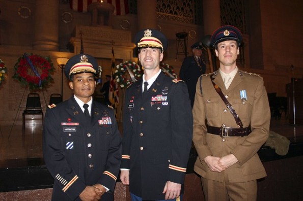
Maj Harrington, Lt Col Morgan (Deputy Comd) and myself at the WWI commemoration
Attending this event reminded me of the other military events I’ve been fortunate enough to be part of during my time here. This includes a battlefield study and trip to Westpoint, a leadership staff-ride at Gettysburg, and a trip to attend a USACE conference in Alabama of all places (where I stayed on a university campus with no bar!). The US exchange first and foremost offers engineering experience (obviously). However, there’s another side to it which shouldn’t be underrated. I’ve found it absolutely fascinating to be part of USACE, to operate with them, and to see how they go about their business. From a military organisational point of view things are certainly different over here, and a year ago when I arrived I found it almost impossible to compare USACE with the Royal Engineers; they’re simply poles apart in terms of structure, capability and function. There are of course some things they do badly. For example (in my opinion) separation of combat and trade engineer skills, which reduces flexibility and increases reliance on non-organic support and sub-contracted work. There are however a number of lessons we might consider paying attention to, for example they are very good at fully integrating their reserves and have an extensive reach-back capability. Overall from a developmental point of view I’ve found the social and cultural emersion to be just as interesting and useful as my day to day work.
Finally, one last photo from the Baltimore District military ball! If there’s one thing we’re undeniably better at it’s uniforms!

Military personnel at the Baltimore District Ball
Contamination Crisis – UNSW
G’day gents (had to do it). Australia has experienced a record breaking 23 days of continuous rain, so I have managed to maintain my pasty complexion. Quick orientation – My site is at the University of New South Wales where there are effectively three separate projects. The main event is the Science and Engineering Building (SEB). The substructure consists of a contiguous pile wall (CFA piling), followed by a bottom-up concrete sub/superstructure. The Roundhouse is a refurbishment (including significant structural steel strengthening) of the University’s precious student union. It’s the oldest building on campus and there is a big push to complete before Christmas for obvious reasons. The Hilmer building is a M&E services fit out project.

Contract arrangements.
Shock – none of the projects has a formal contract. A letter of intent was issued only last week to continue with works on the Roundhouse and the SEB contract is still being negotiated (current works including piling mattress form part of the early works letter of intent). Multiplex are pushing for a Design and Construct (D&B) contract, but the client wants more influence via a managing contractor contract. In addition, the SEB still doesn’t have Development Approval (DA) from the council and the delivery of the piling rig has been pushed to the right by another 2 weeks as a result.
Contamination Issues.
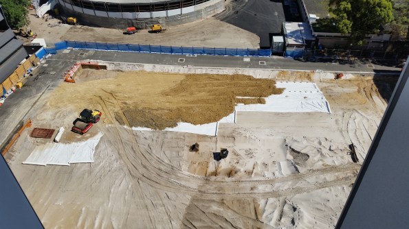
The Geotechnical Engineer found no evidence of ground contamination during his GI. However, whilst the SEB site was being excavated to formation level in preparation for construction of a piling mattress, bonded asbestos was identified on site (believed to be old formwork panels from previous construction that were dumped in an excavation!).
There were 2 potential remedies. First was to employ a hygienist to sift through all excavated material and inspect each load as it left site. Or alternatively just remove the first 1.5m from across the entire site and classify the whole lot as General Solid Waste Asbestos (GSWA). Surprisingly, this was only $2/tonne more than normal GSW and therefore a mere $26,000 of additional cost. The total effort was 13, 000 tonnes of waste material that required approximately 600 “truck and dogs” (Aussie slang for a truck with a large 12 tonne skip on the back). I was involved in producing high risk workshops and removal control plans for the site. Clearance certificates were issued for the site and piling mattress construction has begun.
On the roundhouse, the existing steel structure was covered in lead paint (for fire proofing I assume). This was obviously identified and considered in the programme, but the length of such a process was hugely underestimated. The programme is now 4 weeks behind and only 30-40% of the paint has been removed. The first option considered was to sand blast it off. However, this idea did not survive very long due to the clean-up effort required and the difficulty of containing air particles. The second option proved mildly successful and involved soaking the lead with a gel before blasting off the lead with dry ice pellets in a spray gun. See dry ice pellets and gun operator below.
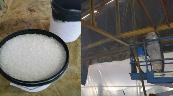
However, although successful, it is a painfully slow process, even after reinforcements arrived with additional guns. Yesterday the subcontractor switched to a soaked paper peel that is applied overnight before being peeled off with ease, bringing the lead with it, the next morning (very effective). Unfortunately, whilst everyone was high-fiving each other, some of the solution dropped onto the leg of one of the workers and it burnt straight through his PPE! All work has been stopped until a new Safe Work Method Statement (SWMS) is produced by the subcontractor and reviewed by MPX. That is tomorrow’s problem…….
How your Great Grandad built a Chimney.
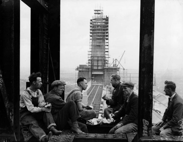
Figure 1: The original construction of Battersea Power Station’s chimneys.
English Heritage had many stipulations before planning permission was granted for the redevelopment of Battersea Power Station, a key one of which was the restoration of the iconic chimneys. These had to be built using the same methods as they were in the 1930s, which has led to some interesting issues during construction.
Jump forming over slip forming.
The original proposal was to slip form the main shaft of the chimney using a smooth form, and then go back and attach the ribs, which are mostly cosmetic and contain no reinforcement, afterwards as well as marking on the day joints (Figure 2.) However, the use of jump forming was enforced as this was used during the original build. This is where the formwork is lifted 1.22m (4 feet as per original design) every other day, building the chimney in a series of rings. This results in the horizontal rings, or day joints, as a by-product. The ribs are cast at the same time during jump forming. Having not been involved in slip forming I do not know if these ribs could be included in a slip form, could someone enlighten me? To ensure that there is an interlock between the pours, the top of the pour is sprayed down at the end of the day to remove the grout and expose the aggregate, allowing the next pour to bind to the previous one.
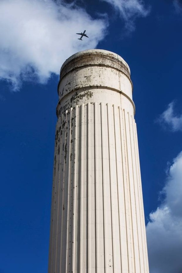
Figure 2: Original chimney, showing taper, day joints and ribs.
The taper.
As can be seen in Figure 2, the chimneys taper as they rise. This is achieved by using removable plywood panels within the outside formwork (Figure 3), which have a slight taper and are trimmed by 1.5mm per side per jump. They are sized to fit between each of the ribs. To make this small cut easier, there are 3 sets of panels, so after each form is used it is trimmed by 4.5mm on each side and introduced back into the cycle. The ribs themselves are a constant size throughout. As there are no ribs on the inside, the formwork is simpler and consists of metal sheets which can slide over each other to reduce in size.
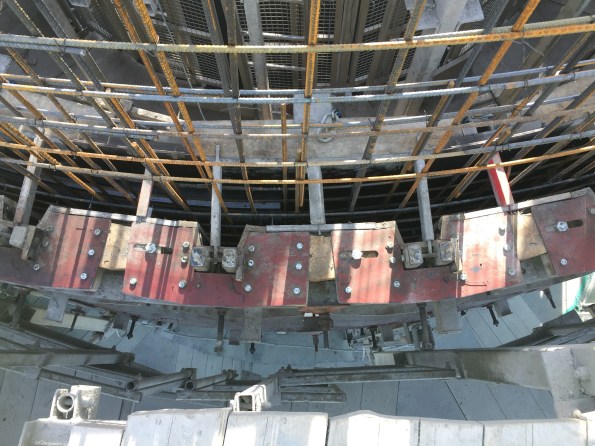
Figure 3: Formwork.
Concreting.
Due to the low quantities of concrete required per jump, a concrete pump was not suitable as more concrete would be required in the hose to achieve the height required than is actually needed in the formwork. Instead, there is a 600L hopper on mini train track installed within the hoist (Figure 4), which is filled from the onsite batching plant (which is purely for the chimneys and can only produce 300L per batch) via another hopper on a set of forks. The hopper is then pushed back into the hoist and ascends. At the top this hopper is used to fill 4 wheelbarrows, which are moved in a one way loop around the top of the chimney, pouring into the formwork via a wooden slide, before continuing around to be filled again. There are two wooden slides (Figure 5) which leap frog each other around the chimney, and despite the system being so low tech, it is remarkably efficient. The workforce of 7 (4 on wheelbarrows, 1 on the hopper / hoist, 1 with a vibrating poker and 1 supervisor / slide mover) quickly pour the 600L into place. Using this system they are now able to achieve 1 jump every 2 days.
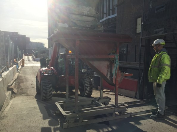
Figure 4: Hopper on tracks.
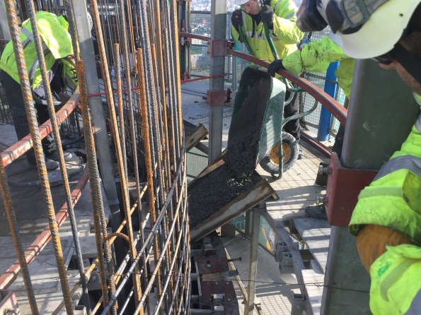
Figure 5: Wooden Slide.
Reinforcement.
This is shown in Figure 3 and Figure 5, and it consists of an inner and outer mesh which is constructed from straight bars every other day, in between pours.
Future use.
There are Halfen channels cast into the inside of the chimneys, as there are various fixtures being installed later on. All will have internal ladders for maintenance, one will have 5 flues for the various plant rooms across the development (so that the chimney will “smoke” once again) and 1 will contain a glass viewing platform in a lift which Willy Wonka himself would be proud of, as shown in Figure 6.
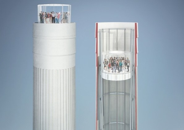
Figure 6. Glass Elevator in the North West Chimney
Summary.
I think that this construction method proves two main theories; keep things simple where possible, and that repetition will improve speed. Firstly, I think that there will always be a place for the simple, low tech solution in construction. Although simpler methods may not be as quick as more modern techniques, the potentially low set up cost and running costs, coupled with the speed at which they can commence, could often offer a more affordable solution. Clearly this may not be the case if the task is on the critical path where time is likely to be the main driver. Secondly, where things can be designed to be repetitive, they should be. There are a total of 4 chimneys to be restored, each requiring over 40 jumps. The overall process is becoming slicker each jump, and although the crew quickly reached the maximum allowed rate of 1 jump every 2 days, the total working hours to achieve this has reduced.
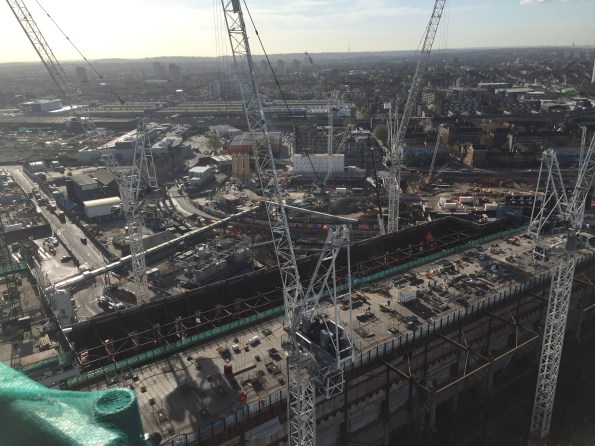
Figure 7: The view from the top (looking at the NLE.)
The chimneys are now finished, and a construction enquirer article has been written.
http://www.constructionenquirer.com/2017/06/05/two-year-rebuild-complete-of-battersea-chimneys/
Acoustic barrier
I’ve been working on a project designing a variation of a demountable acoustic barrier for use between the entrance to TFL tube stations and busy roads. It uses a new noise attenuation cassette produced by Echobarrier and potentially geopolymer or wood concrete base units and a titanium dioxide additive to the surface to reduce NOX levels.
The basis of our appointment is initially to act as structural engineers on the design and installation of a prototype. The total budget for design and construction is 300k. The real money will be made through IP rights and by successfully developing the prototype into a system that can be deployed more widely. For this reason the project is relatively confidential so please don’t discuss outside the course (not that anyone is interested anyway).
Due to the low budget, initially, we need to stay close to existing systems to assist with the client risk appetite, ease of installation etc. But we also need to demonstrate options for increasing beauty, function, speed of deployment, improvement to pedestrian safety, longevity, flexibility etc. and to that end i’ve had initial discussions with the architects and a small pre cast company specialising in low cost prototypes, and BRETT Group for delivery of a scaleable solution.
So far i’ve looked at design actions and produced the structural basis of design. All relatively simple stuff. Future work will look at the options for the concrete bases, and detailing for the connections between the posts and base (likely to include a cost comparison of bespoke cast in channels, and off the shelf resin anchor systems.
The snag is that funding has been put on hold currently, but we should get news later this week from the Client on when it might be re-initiated.


Pipes and shit
Whilst I’m pleased to see the Phase 2s on here so the Phase 3s can now wind down the blog contributions, I think RF is under the impression I may be hiding under a rock again, so below is a brief summary of some of the work i’ve done recently using a calculator and felt tip pens. They’re all work in progress so feel free to comment with any suggestions, advice or queries.
Selfridges Drainage Management Plan
Below is the latest of 4 technical notes i’ve produced as part of the Selfridges Drainage Management Plan. They’ve let their drainage get in a bit of a mess and there are literally places where shit has hit various fans (or more importantly some expensive handbags). Expedition were initially engaged to summarise the issues. They reviewed the drainage systems and produced 20 recommendations thinking that Selfridges would say thanks but no thanks. Un/Fortunately depending on your perspective they turned around and tasked Expedition to enact every one of them. There started 2 years of work for the civils team charged out at 15k per month. What a terrible example of poor asset maintenance I hear you cry! But is it really? £15k is probably two of their mid range handbags….retail space is worth a hell of a lot more to them when it’s operating than when a contractor has some hoarding up so they can do maintenance. In retail, as in construction, decisions are made on a commercial basis, and sometimes this trumps engineering factors. If you can’t understand a seemingly ludicrous engineering decision, make sure you’re considering all the wider factors.
That said their latest idea to put a new toilet block on a part of the system that’s potentially already overworked (the exact drainage routes still aren’t known) seems truly crazy, and the work below (still in progress) is me trying to work out exactly how crazy it might be, and how to politely tell them.
EXP 326-4 Outfall 2 Assessment[2015]
Taipei Airport Drainage
Expedition are completing the concept design for the drainage masterplan for a new terminal at Taipei airport. The detailed design is being done by Arup.

I was looking at the structural support for the downpipes. There were a number of constraints. The design requires twin stainless steel downpipes (circa 500mm diameter) to be supported from the roof truss and at berm level, but unsupported between so they resemble steel columns. Large thrust forces will be developed at the pipe bends, high wind loads are expected, differential movement is expected between the roof and the ground (+/-45mm horiz. and 15mm vert.), seismic effects must be considered.
I initially looked at cantilevering the pipe 8m from the ground to alleviate the differential movement issue, which required me to assess the dynamic response of the pipe to the expected wind load, and the thrust of the water hitting the top of the hopper. However the lead engineer wasn’t entirely uncomfortable with this, with too many variables for us to mitigate the risk without unwarranted analysis at concept level, so I then had to look at options for supporting at truss and berm level.
The latest (although potentially not final concept) using WGS 77 Victaulic couplings as a “flexible” (the meaning of the word here is relative as their flexibility is limited 9mm per m length) is shown below. Although we calculated the forces and specified the couplings we omitted this from the concept document. We’re not paid to develop detail so why take on the liability. I also got slapped on the wrist for writing “WGS77 or similar”. Despite seeing this approach numerous times on site it’s avoided in the design office as it opens up all kinds of legal issues if a “similar” product fails.


