Archive
How much reinforcement is too much reinforcement?
I draw your attention to the photos below as an illustration of the problem. It shows the quantity of steel being installed both longitudinal and transverse.

Photo 1 – B40 Longitudinal Bar (The steel coming towards the photo is the bottom longitudinal steel at the end of a beam)

Photo 2 – Transverse Reinforcement

These beams are at the B01 level in the Battersea Station Box, in places 3.8m deep, acting as transfer beams for the over site development. They have been designed for point loads of up to 10MN, transferring the load to plunge columns.
If I now break this into two:
Longitudinal steel – The quantity of longitudinal steel in places is greater than the 0.04Ac. I thought this 4% figure existed to prevent brittle failure and allowed tension cracks to appear in the concrete prior to the beam failing. Therefore, if this is the case then what are the implications of a design such as this?
Transverse steel – Looking in the guidance for the minimum spacing of transverse steel, the distance should be 20mm (10mm aggregate) to form a bond between bars. Clearly this does not, therefore I see three problems potentially arising. Firstly a proper bond will not be able to form between traverse bars; does anyone know what implication this will cause? Does it mean a reduction in shear resistance? Secondly it does not allow for vibrating pokers to be lowered into the concrete at this location during casting and thirdly it acts as a sieve during pouring, causing separation in the concrete. All of which are mentioned in the codes when designing transverse steel.
Looking into the detailing a bit further I discovered in the IStrutE detailing guide, the table below shows the difference between size and diameter of bars. Apparently one should not confuse size with diameter, after all a size 40mm bar is 46mm in diameter. Therefore when this transverse steel was detailed, if the size was assumed to be the diameter, all those millimetres add up to the situation in the photos above.

Service clash and visualising drawings.
The East Office at Hinkley Point is a 13,000sqm building formed of 12m x 3.6m x 3m modules. Currently undergoing first fix services it is the furthest along of three similar structures on site – it is not yet water tight but that is a different issue.
This post is just to quickly share the issues that have been experienced on my area of the site regarding service clashes, particularly drainage.
A 3D model was constructed for the building – clash detection was said to be acceptable. Foundations were constructed by another contractor on a contract with the Principal Contractor. The modular building contractor approved the as built strip founds by survey prior to beginning install of the modules stating that the greatest disparity in the service pop ups was +/- 40mm.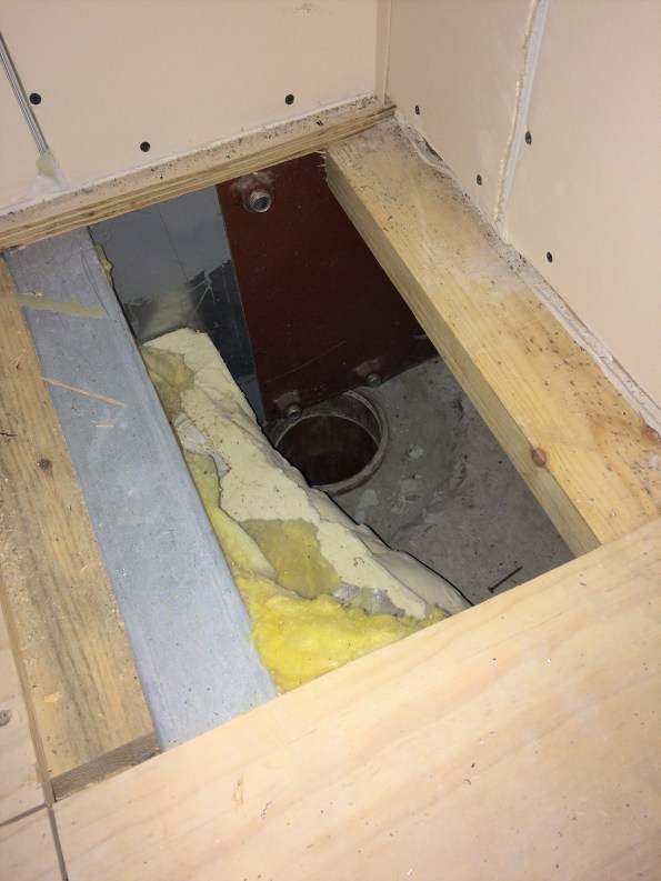
The intent was for vertical soil stacks to connect directly into the waste pipes from WCs in the corners of each unit. This did not account for the steel plate in the corner of every unit to allow attachment of plasterboard or for certain units to have their beams sit directly on top of the service pop ups. I advised (as PC we can’t do anything else) that they cut holes in the plate, as they were going to install a series of flume like bends which would mean additional boxing in. It also meant the plumbing sub contractor taking on risk from straying from the design which was unfair on his part.
Also, I think John mentioned always to check cross-sections rather than just look at plans. I have seen this first hand as a kitchen extraction duct is being installed that allows only 2.2m headroom, not including a floating ceiling to be installed. The spin off from this is that if this duct is not changed it creates a ceiling void above 800mm depth, thereby requiring fire detection or sprinklers. The duct also (as everyone who has seen it agrees) looks odd. Which has been enough to get the designers down to have a look this week. The duct is extraction for a reheat kitchen, yet it is twice the size of the same piece of kit for a proper kitchen in an adjacent building. Maybe a spec issue or stray decimal point.
The M&E, although not what I wanted to be involved in, has been an education in project life cycle and the importance of understanding what drainage goes where prior to casting concrete, signing off surveys, properly visualising the end result of an asset or committing to a design in the case of the extraction ductwork. With time pressure it is not as easy to be as thorough in some areas viewed as less critical but it is often the details that cause bigger problems from what I have seen over the past 7 weeks.
Hoping to get mud on my boots soon or at least within touching distance of a bit of plant (within the safe zone, having filled out the requisite forms etc).
