Pingo Bingo
Last week Beresford tricked me into attending what I thought would be a notoriously dull lecture at the Royal Society of Geologists. The talk was on a ground condition known as a Pingo, or using its more technical name, Drift Filled Hollows. It turned out to be mildly interesting because the ‘expert’ openly admitted that Geological understanding of this condition remains relatively basic at the moment and from engineer’s perspective, the implications for a large structure are potentially very severe.
To try keep this short, a Pingo is basically an unexpected disturbance and variation in the ground strata caused by (they think) perma frost occurring in the ground some millennia ago. This created a hole which is then essentially filled with differing material over time. In the London Basin this is an issue because it means, where you might expect to find a decent band of London Clay there could actually be a column of terraced gravel, or another material, penetrating to significantly greater depth.
The following image shows a cross section of the anomaly discovered during the Blackwall Tunnel project.
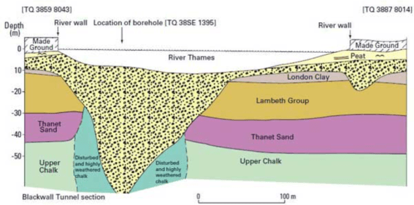
Some of these anomalies have been found to be more than 90m in depth and have relatively small surface areas. This is potentially a problem because if you insert a large load bearing column designed to use skin friction from the London clay, Lambeth group or Thanet sand, and it actually sits within a deep column of terraced gravel, the performance of the pile could reduce significantly. An Engineer in the audience stated that if you double the Pour Water Pressure the bearing capacity of the pile roughly halves. Clearly permeability in the terraced gravel is considerably greater than the clay.
This issue is even more of a problem because you could conceptually have a Pingo anomaly positioned between site bore holes. This means that you might be unaware of the issue on site until the point the pile is being installed. This is obviously too late in the day simply because by the point piles are being installed the design of the building and its foundations should have been finalised.
As I left the lecture it occurred to me this might make a decent thesis topic for a phase 2 student currently struggling for ideas. It looks like the Geologist lot are working hard to collect data on this issue. Combining this data with a detailed look at the risks a Pingo presents from a civil engineering perspective might prove interesting.
Laurie’s added site product from Phase 2

TD,
There was no trickery involved in fact I suggested not attending in favour of liquid refreshment. However having mulled the lecture over, particularly the point about pwp and pile capacity I have been wondering how Nine Elms is designed to deal with this. I mentioned in my first post that Nine Elms has a scour featur/pinto/DFH on its Eastern boundary and there are some significant load paths taken down via transfer structure to piles in this mixed up material. Clearly a reduction in shaft resistance due to a change in effective stress (increased pep) would result in a larger proportion of the load resisted by the base and a therefore disproportionate increase in settlement. The basement raft is 3.5m thick RC which I had assumed was for heave reasons (12m of soil has been excavated for a basement), this would clearly be beneficial for load sharing as piles settle. However here I see piles in the scour feature settling significantly more than the other side of the stucture, causing all sorts of issues. Maybe this is something I will quiz the designers on.
The above is merely my reflections on my site, it is a shame the lecture didn’t cover some advice to engineers on sensible assumptions to make ref material properties and FOS to aim for in foundation design.
There’s an argument that says a good piling engineer will spot the arising being at odds with expectation and a Good resident engineer will quickly determine the need to reposition and provide a bridging structure so do a fag packet calculation and adjust the cut off to give enough depth to fit it in. Of course if you don’t have good engineers on site and are a PM organization you’ll crack on and try to find the solution after you’ve messed up the location, created additional problems and wasted a lot of time. Then you’ll whine that engineers aren’t very helpful and cost a lot and so should be kept even further away from site… There’s a TMR in there alongside the more useful thesis about what the best QRDs might be.
Rich, I am on site so your quality of engineer onsite comment is valid. From the SI it is clear that there scour feature and the pile arisings have been classified. I think the issue is how to interpret soil properties to use in design given the variable nature of the features. Current advice is to half the Cu for clays and take a reduction in the strength increases with depth, it is in soil design parameters where I think a thesis may have legs.
Brad,
I therefore have great confidence in the engineer but not the freedom he might be given. Being present is one thing, being engaged and heard in the decision making process is another!
I agree with the area for thesis study entirely. The point in looking at the soil properties presumably would be to be able to establish them as soon as possible and therefore to be able to take some sort of deliberate action, which would be where the useful output of such a study would lie. It’s definitely a JM topic and one I think you’d both enjoy!
Yes Richard McClure’s site was affected by the presence of a scour feature…in that case they knew it was there they just underestimated the depth (no geophysics following bh identification). So when it came to casing, through the essentially coarse grained feature, they ran out of casing and had to extend by welding.
As to the pile performance – I think there is no clear answer..IS the pile performance better in the infill material or the clay…it is not clear. Certainly if the feature can fill with water ( bounded perhaps on a less permeable material beneath it) then the vertical effective stress is reduced and the lateral effective stress is reduced and so on…
Years ago I came across one of these things and here is what we did…
We vibrated in the casing ( increasing the relative density of the feature material ( so K and tan delta all go up) ….we cfa’d beneath that under fluid….We carefully continued pumping to the bottom of the casing and then withdrew the auger. We then vibrated then plunged the cage and pumped in the balance of the concrete as we vibro’d the casing out… I’ve not heard of it done since but I reckon the pile performance in the upper pile was better than the pile through the clay beneath…We did load test and I can’t recall the results
There seems to be an assumption that the infill is always of poorer performance then what is replaced…..errrr… I can’t see that this is necessarily the case.
John, there has been a number of test piles conducted on One Nine Elms. I will see if I can get my hands on it. Back analysis of strains will give an estimate of load reduction in the pile and therefore soil performance?
TD,
I found this quite interesting, so much so that I decide to consult the Project Risk Register on the NLE. My site at Battersea is within the zone that you described and I believe there are scour features on the other Battersea sites.
The only item on the risk register relating to the Battersea Station Box lists ‘unexpected hollows’ with a post mitigation value of £300k.
The tunnels running to Kennington are located in the London Clay, therefore if a Pingo was hit this could potentially be extremely hazardous. Firstly it would delay tunneling because of the different soils and secondly it could cause flooding. The post mitigation combined value of unforeseen ground conditions for the remaining four items on the RR relating to tunneling is £590k. Arguably this could be perceived as a low value for such a project unless you were very confident on your knowledge of the ground.
Turning to the GDR, Periglacial scour hollows are listed on the GDR RR east of Battersea, the mitigation which followed was a thorough investigation using multiple boreholes, identifying the extent of two scour features. The alignment of the proposed tunnel was then positioned between the two features. (I do have a nice contour map but it wont upload into this comments section)
I suppose only time will tell if the GI has mitigated the risk sufficiently.
H
Henry, those costs do seem remarkably low for a risk than potentially has such significant, programme consuming implications. They either know a lot more about this than you and I or just put a nugatory figure in their contract without thinking about it. I know which of these options I’d put my money on being the accurate reality.
I fear you might be right Tom but it’s worth remembering the value allowed in contingency is generally the estimated cost of dealing with an emerging issue multiplied by the risk of occurrence. So, if the extended GI has reduced the expectation of encountering an issue to 10% the contingency allocation will be that proportion of the expected cost of dealing with it. The idea is that when you add up all of the contingency you end up with a figure that represents 100% of what you will need to shell out over the course of the job, you just don’t know for certain where. This is of course turned to rats when a PM notes that a risk has passed and reallocates the contingency associate s because that sum should remain available for other downstream risks yet to emerge. Now the very sharp will note that there are flaws in this methodology and I accept it is crude and inaccurate but it’s one I’ve encountered!
It is also interesting to have a scan at the contract documents from the commercial perspective.
BBGE (with their experience at Nine Elms) were not for getting stung again so they changed the contract to state 1m difference from design borehole as opposed to 3m
Thy were then quids in when they hit different ground conditions (which were know about but not the precise extent of the difference).
It should also be noted that the presence of the pingos/scour feature (two different anomalies) can be reasonably well predicted from SI – just not the extent of them.
For example, there is an area south of the river where scour features are prevalent – I cannot remember the precise details but hence BBGE’s caution
Battersea Power Station is also built directly on top of a DFH, and although the size and position of it is relatively well established, we still get frequent deviations of up to 6m. This presents some interesting challenges. The depth of London Clay across the Boiler House (the main building where I am piling) varies from -5.4m to -31m, with the steepest change I have encountered so far being clay levels dropping by 15m between 2 adjacent piles, located 6m centre to centre.
Our ‘normal’ build sequence is to case down to seal in London clay, (usually around -8m) then dig to -38m without fluid support, before flooding with bentonite and continuing to dig to toe depth of around -60m. However when the clay is deeper than 12-15m (depending on the size of the pile and exact local ground conditions) we are unable to case down to clay, so we have to flood with bentonite early and dig under fluid support from there.
The tender price is primarily based on the clay level. When the clay is expected to be below the possible casing depth the work has been priced accordingly, but when the clay is deeper than expected this adds a large time and financial cost – digging under bentonite seems to take up to 3 times longer than digging without it.
In terms of design, all of the 255 piles within this area have been designed in advance for the design clay level, as well as 12 further designs with clay at 0.5m intervals beyond this. This means that as long as the clay is within 6m of the expected level, we can select the correct design to continue with minimal delay, and no wait for a redesign. Generally the ‘redesign’ is just increasing the length of the pile, usually by roughly 0.5m for every 1m deeper than anticipated the clay actually was. Any increase in depth does still result in a cost, but importantly the programme delay is minimal.
I am also considering a Thesis or at least a TMR on this topic, but including programme and cost elements as well as technical issues so I may be able to add more detail at a later date once I have completed more research.
Laurie,
That is a huge discrepancy of level over a short distance. The unknown boundaries bring a very large risk, have you looked into the financial allocation to the risk? I would hope it is more than is allocated on my site!
H
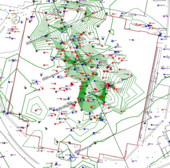
I have added a drawing showing the outline of BPS and the DFH details to the media section if anyone is interested.
Laurie
The financial aspects would be very interesting…
We had the exact same pile redesign scenario – just add some extra length HOWEVER whilst 1 m could be easily spliced on site anything longer required new cages with a considerable lead in time and associated cost?
Gents, it sounds like a significant number of you are actively dealing with this issue on phase 2 with alarming frequency.
Thanks Laurie, I have added your product to the bottom of the article for reference!
This seems to be an issue cropping up all over London, so I have a couple of final thoughts. The meeting made it clear that Geologist boffins are still trying to determine where all the DFHs are located. As London continues through its mental regeneration process many of them are only just being discovered, partly because piles and excavations are ever increasing in length/depth due to advances in Building design. Secondly, as Laurie indicated the change in material/ground strata can be extreme even between relatively close posns. Knowing that, it raises the question of how many SI boreholes, given the dangerous implications of constructing through an unknown DFH, is a sensible number? Clearly this problem suggests the more the better, that said a sensible balance with cost/programme is required. I’ll leave you clever phase 2 chaps to ponder this still further.
Enjoy
TD