Archive
SLOPE STABILITY ASSESSMENT FOR TOWER CRANE ERECTION
Apologies for the long winded explanation that follows this intro! In summary, I have a slope stability problem and if anybody could provide solutions in addition to the ones I’ve suggested below that would be great. My solution also requires fill that I assume would need to be compacted? Has anyone done any work on compacted effort required in coarse grain soils? Any other thoughts appreciated also.
My primary responsibility at the moment is managing the construction of the tower crane for the SEB site. This has principally involved managing and coordinating contractors to ensure that all enabling activity is completed for this Saturday (1 July 17).
The tower crane will be constructed in sections through the use of another 300 tonne mobile crane. Figure 1 below shows the site layout for the tower crane construction. The main boom arm will be constructed on the road before being lifted into position. The red highlighted area shows the extents of a slope which separates the two construction zones (North and South) and the blue highlights the outrigger pad areas.

Figure 1 – Site layout for tower crane construction.
The crane company are required to complete a lift study for the exact location of the crane in order to accurately calculate their maximum boom radius and resulting loads that will be transferred into the ground via the outriggers. During planning the location as shown in figure 1 was agreed and a lift study was completed by the crane subcontractor. The resulting loads were 90 tonnes through each outrigger, which with pads of 2.5 x 2.5 m creates an operating stress of 144Kpa (I conducted a quick bearing capacity check for the loose sand layer to 2.5m which produced a stress at which failure occurs of 360kpa. No FOS!). One of our contract clauses requires MPX to complete DCP testing for any activity requiring outriggers. It was only once the positions of the outriggers were placed on the ground that I realised that we could have a possible slope stability issue. The image below shows the profile of the slope and the position of the mobile crane outriggers.
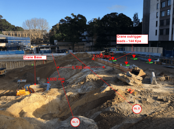
Figure 2 – Current slope profile and position of 300T Mobile crane
The proximity of the outrigger pads to the crest of the slope was a concern. The geotechnical engineer had also specified batters of 2:1 (H:V) throughout. The slope was clearly not 2H:1V. It was almost 1:1 with reduced level (RL) at the top of crane base of 24.000m AHD and a RL of 29.000m AHD at the top of the slope.
Transferring risk is the Multiplex way and the decision was made to get the Geo consultant (Coffey) to inspect and approve a solution. They will be visiting site tomorrow!
Smelling an opportunity to conduct some much-loved geo analysis, I immediately leapt into action and retrieved my John Moran Slope Stability notes in order to see if the current slope would be safe. About an hour or so later I realised that I was stumped. I understood the Bishop’s method of slices, but I couldn’t see how to model the surcharge load created by the crane outriggers (any advice would be appreciated).
I eventually decided to go back to first principles and use the equilibrium equation ∑M = 0. The idea was to take moments (resisting moments divided by disturbing moments) about the origin of the slope to determine a factor of safety (FOS).
Assumptions:
- No GEO reduction in soil parameters. All ϕ’ values etc taken from Coffey’s GDR.
- GWL is at measured mean levels (22.6m AHD) and therefore no pore pressures considered in calculations.
- Failure would be a circular slope within the loose sand layer (this was also based on the fact that the pile cap would provide toe stability and additional anti-clockwise moments about the origin).
- No consideration made in hand calculations for DC1 or DC2 i.e. factoring the soil parameters of loads.
Figure 3 below shows my hand calculations for the existing site conditions. The FOS was 0.91; so a risk that the slope would fail if not modified.
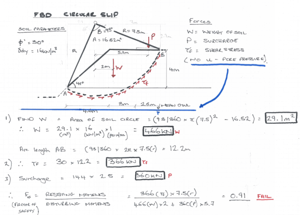
Figure 3 – Slope stability hand calculations for current soil profile.
When looking at solutions to this problem I could see 2 possible solutions:
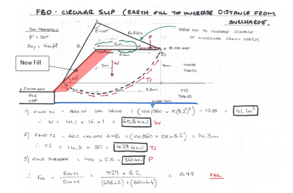
- Place additional fill on the slope to increase the distance of the surcharge from the crest to 5 metres.
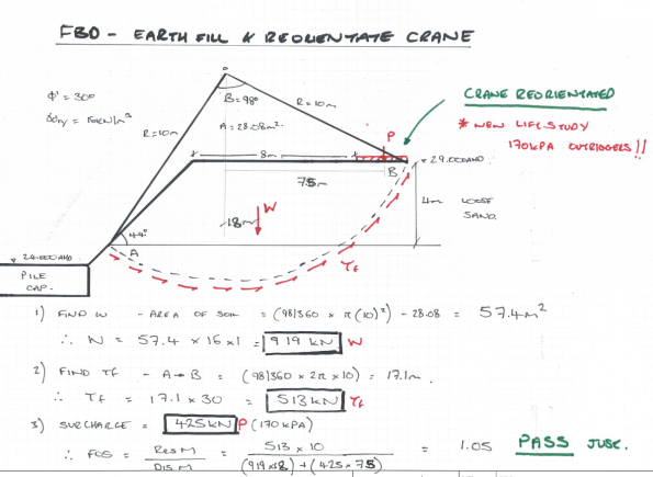
- As above, but also re-orientating the crane to further increase the distance of surcharge to the crest (This required a new crane lift study as boom ranges would increase; this was completed for contingency and outrigger stresses increased from 144Kpa to a maximum of 170Kpa).
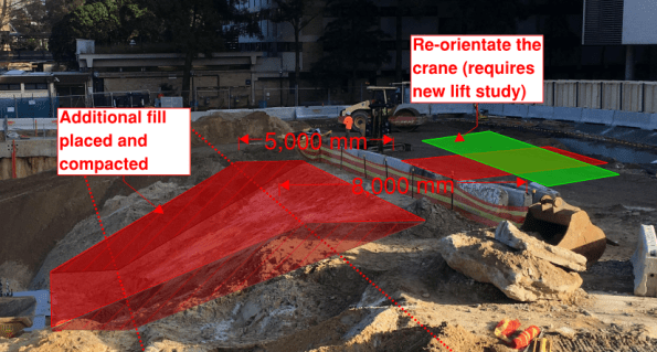
Figure 4 – Potential solutions on a mark-up.
Solution 1 Calculations – Build up slope with fill only (FAIL).
Solution 2 Calculations – Build up slope with fill and re-orientate the crane (PASS –JUST).
My results showed that the crane would need to be re-orientated and additional fill would need to be placed to increase the distance between the surcharge load and the crest of the slope. Mindful of the fact that my hand calculations may not be entirely accurate, I also checked on GEO5. Results are shown below, generating similar results for the current profile but passing on both solutions (only just passing for solution 2).

Based on these calculations I would suggest that the distance from the crest of the slope to the outriggers needs to be increased by placing some additional fill and by re-orientating the crane. The lifting will also need to be monitored very closely to ensure that loading conditions don’t increase (i.e. lifting study boom ranges are not exceeded) and the outrigger plates are the correct sizes. It will be interesting to see what the Geotechnical engineer comes up with tomorrow.
