Archive
Planes, Trains & Automobiles
The Airport East project has displayed the importance of management of stakeholder relations to ensure the smooth running of a site.
Roads and Maritime Services (RMS), Australian Rail Track Corporation (ARTC) & Sydney Airport Corporation Limited (SACL), are the three biggest stakeholders on the Airport East site and known affectionately as the three amigos. The contract is construct only and a number of clarifications are submitted to RMS daily, which in turn do lead sometimes compensation claims. SACL own the land but also impose tight restriction on operations due to the proximity of the E-W runway. ARTC operate the main freight line which runs to Port Botany which dissects the site and is also being upgraded as part of the project to dual lines, they also impose tight restriction and limit access to the rail corridor.
During installation of reinforcement for Span 1 of the Canal Bridge, RMS were still changing their minds right up to 3 hours before the pour of where they wanted to locate conduits for traffic lights and lighting for the bridge. Retrospectively fitting conduits into slab reinforcement is a time consuming process. This is a lesson I will be taking forward for when the ducts are fitted into the Rail Bridge for post tensioning. It is key reinforcement is staged with conduits or ducts being fitted prior to the B layer of reinforcement being placed.

Figure 1 – Conduits for traffic control systems run through the cast-in-situ bridge deck of Span 1 of the Canal Bridge
One of the most exciting yet exhausting tasks I have been package manager for on site has been the installation of sixty precast pretensioned bridge beams for Span 2 of the Canal Bridge. I have taken this process from competitive tender, standard subcontract and award, through to installation. The tasks leading up to their installation involved; authoring the activity method statement, excavation and removal of the temporary piling platform in the canal, checks to stressing calculations for the bridge beams, quality inspections of the prestressing yard, application to SACL for a week long closure of the E-W runway for 220T telescopic crane, design and validation of the crane platform, oversized load permit for delivery to site of the beams, organisation of haulage, medium risk lift plan for installation, and being lead engineer co-ordinating the landing of each beam onto temporary bearings. Choreographing their installation over 4 days, involved 15 being delivered per day, a truly rewarding task once they were all secured in place.
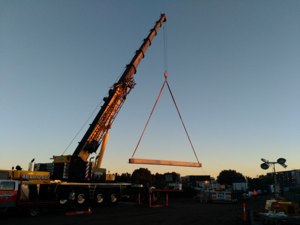
Figure 2 – The one of sixty precast bridge beams is lifted into position for Span 2 of the Canal Bridge
During installation I received a telephone call from SACL, the wind had picked up so for safety reason they needed to reopen the E-W runway. 15 minutes after the crane was lowered, the photo in Figure 3 was taken as an A380 passes over the site, showing the reason for the imposed height restrictions. This delay forced installation operations to cease until that evening when the Airport closed between 2300 – 0455hrs.
 Figure 3 – SACL reopen the E-W runway of Sydney Airport during installation of the beams forcing installation operations to be postponed to the night.
My relationship with ARTC will grow as I move onto Project Engineer for the Rail Bridge and Underpass this month.
Beams with a twist
I would appreciated peoples thoughts on the below issue I have encountered on site.
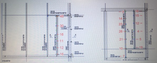
ISSUE: The steel frame erection is generally progressing well on site with approximately 90% of the steel work now erected. Unfortunately a recent site inspection highlighted that some of the secondary steel beams to level 02 had developed a twist in the member (see below). Level 03 above is a cantilevered deck which is currently temporarily supported through diagonal bracing.


The tolerances for the steel work on the project are laid down in the Structural Steel work Specification developed by Ramboll. These are in addition to the requirements of the National Structural Steel work Specification (NSSS). However, establishing the tolerances for the twist has proved more difficult than first thought. The steel contractor is currently attempting to determine a root sum squared answer from the fabrication and erection tolerances. In the meantime the visual distortion has been enough to instigate further investigation.
An as-built survey conducted by the steel work contractor confirmed the following ‘out of tolerances’ for three of the beams highlighted on site.
OPTIONS: The two options as I see it are to either leave it as it is, or to release the members and conduct remedial works as necessary. In both situations an evaluation of the significance of the twist is required to be made.
- Assess the structural significance of the twist. If not significant then do nothing and except the visual impact.
- Assess the structural significance of the twist. If not significant then do nothing, but weld a plate to the bottom flange in order to mitigate the visual impact.
- Assess the structural significance of the twist. If significant, release the connection. Relocate fin plate on primary beam to accommodate altered position of the secondary.
We are currently finding that, possibly due to the consequences, neither the structural engineers nor the steel subcontractor are willing to comment on the structural implications of the twist to the members and subsequently commit to a strategy moving forward. We are due to remove the temporary bracing in the near future. It is hoped that this along with the erection of the cladding will counteract the twist, however it is unlikely to counter it to the extent required.
It would be interesting to hear the thoughts of others with regard to the issue and potential remedial options? I would have thought that this issue must have been encountered previously through the experience of others? Any feedback is appreciated. Cheers, Al.
Backpropping puzzle
Issue. So the concrete frame sub-contractors TWD made a slight error in his backpropping calculations. Unfortunately when interrogating the structural loading document for the permanent design he forgot to subtract the selfweight of the slab and therefore overestimated the capacity of the slab in the temporary state (Figure 1).

Figure 1 – Backprop design
In the permanent design the intermediate slab is designed for a dead load of 7.4kn/m2 and an imposed load of 2.5kn/m2 (Figure 2). The dead load includes the selfweight of the slab, therefore the spare capacity of the slab at present is 2.5kn/m2 of imposed load and 0.5kn/m2 of dead load as the services are yet to be installed. Therefore, by inspection the intermediate slab is overloaded as the TWD requires 5.88kn/m2.


Figure 2 – Loading details
After a bit of research I found ‘The Temporary Works Toolkit: Part 4 – An introduction to backpropping of flat slabs‘ published in The Structural Engineer. This details how for flat slabs below 350mm a simple percentage of load transfer method can be used for calculation of loads in the slab and props (figure 3). This is the method used by the TWD in the calculations above.


Figure 3 – Method 1 for slab and prop calculation
Due to the limited capacity in the permanent case design, this method of backpropping is not acceptable.
Options. In order to solve the problem we could either change the permanent design or the TW design.
Change the permanent design. This option isn’t really possible due to the additional re-design costs and the fact the intermediate slab is 30% complete.
Transfer load to the ground bearing slab. If the backpropping is set up leg for leg with the formwork above then the load could be transferred to the ground bearing slab (Figure 4) . However, as the load is applied the props would shorten and therefore the slab will deflect and it will therefore take some load also. In order to ensure this load is not excessive could you calculate the elastic shortening of the prop and then pre-tighten the prop to minimise the intermediate slab load?
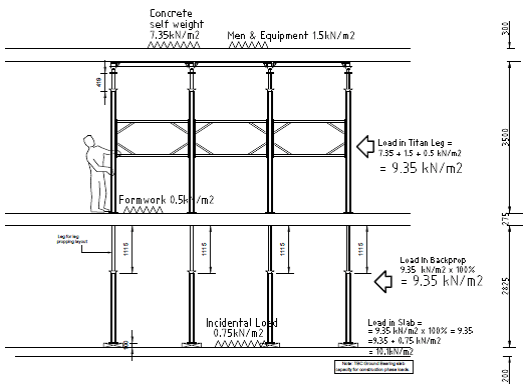
Figure 4 – Backdrop redesign
Grateful for any thoughts or observations on the logic above. Also, from others experience, is it normal that there is so little capacity in the permanent design to allow for the temporary construction state?
Groundwater Disposal
Issue
Keltbray have commenced their bulk dig to B2 level in Zone A of The Stage, Shoreditch, experiencing silty gravel down to clay. Although not scenes from The Tempest, they are experiencing groundwater seepage with the following photo showing what was experienced over the course of one night (having left the excavation dry at the close of works yesterday, and yes I have raised the issue that if someone is working that close to deep water it should be barriered off and have rescue means in place).  The Keltbray RAMS had a plan to deal with groundwater by managing with sump pumps before installing a full dewatering system, discharging to Thames Water drainage via sediment tank on the suspended slab above. The issue here is that Keltbray have got a discharge permit in place but not a connection to the manhole for the water. This poses the issue of what to do with the water?
Source
The excavation sits on top of an approx. 15m thick layer of London clay and is surrounded by a secant pile wall installed by another piling contractor before Multiplex took over the site. The wall has a number of out of tolerance piles and gaps in it (as previously blogged by Fred Kiddie). There is also an adjacent Zone B currently at B1 level which has a contiguous wall separating the zones, therefore gaps between the piles. This means there is about a 5m head difference in the zones. My assessment is that this groundwater is flowing from Zone B to Zone A due to the newly established head difference. There is also the likelihood of groundwater flowing from outside the site, passing through some of the gaps in the secant wall into the excavation ie finding the shortest flow path. The site is in Hackney and is located in a former mainly industrial area with mixed uses for the land around. This means to me that there is a fairly high chance of some contamination in the groundwater. The final option for where this water is from is that the pilers have been experiencing more polymer being used in Zone B piles than has previously been experienced. This could mean that the new head difference from the excavation could be causing more flow from the polymer fluid out of the pile and into Zone A.
Options
Option one was to sump pump the water to a hole in the excavated material before mixing it with the spoil and removing using muck-away trucks.
 Issues with this option:
- It is a slow process.
- Some of the water flows back into the excavation.
- The muck-away trucks leave a trail of wet dirt on the road with very wet spoil being carried in the trucks – likely to cause complaints locally from the dirty roads even with one road sweeper employed full time.
- Each muck-away truck is tested for contaminants which would pick up any issues with contaminants in the groundwater.
Option two was to use the polymer pump and pump the groundwater into some of the polymer tanks and use it with the polymer for the ongoing piling. The polymer tanks can act as sedimentation tanks and ultimately conserves using mains water.


Issues with this option:
- Much faster at pumping the water from the excavation compared to a sump pump therefore making the excavation safer, quicker.
- The large amount of fines in the water cause the tanks to block up over time. However, these fines are contamination if not filtered out.
- The water needs treating to increase the pH before being mixed with the polymer.
- The water needs testing for contaminants as you could potentially be putting contaminated water down a pile and into a separate groundwater course much deeper down, causing wider contamination issues.
- There is a limited volume of the tanks for removing the groundwater as the piling ultimately reuses the water.
- The tanks don’t fully act as sedimentation tanks as their outlet valve is at the bottom therefore fines will pass through.
Summary
I have been discussing with the sustainability team here on the project who have cautiously approved the polymer tank method as it sort of allows for sedimentation of the water. The water isn’t currently being tested for contamination and the volume of the tanks has nearly been used up. I will be inspecting the water for any traces of polymer this afternoon to see if this is the source. If it is, then recycling the water through the polymer tanks isn’t such a bad option.
This issue only exists because a connection to the manhole has not been established yet. This is an item which is sitting with the local council and is an ongoing task to get approval.
Always Interrogate Loads Part Two!
After Brads post last week I thought I’d jump on the bandwagon and descried a similar load related situation we unraveled last week.
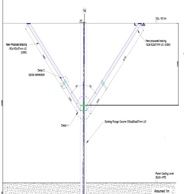
The D-Wall for the Station Box at Battersea was installed last year and contains a number of plunge columns. When installed one of these plunge columns was put in 40mm horizontally mis-aligned, and at an angle amounting to circa 100mm out at depth, then to cap it off the concrete for that D-Wall section was thought to have been poured low.
This results in a design for temporary bracing, to be installed to reduce the effective length during the temporary construction stages.
Everyone on site knew this bracing needed to be installed but no one had really questioned why and if there was another method to brace the column. I initially put forward two suggestions:
- Brace the column from the permanent works below, thereby reducing the requirement to lift the UC bracing sections and drill and fix into a soffit at height.
- Why couldn’t we just cast the RC encasement now?
Although I quickly disproved my own ideas it led me to look at the calculations, and the design behind the bracing. It turned out that the column failed in the buckling check by 118%. However the load case on the column included a temporary road/platform which no longer was going to be constructed. This temporary road added 1300kN to the axial load of the column therefore once this axial load was deducted, the column passed the buckling check and the bracing was no longer required. This was subsequently agreed by our TW cell and the Designers.
From a H&S point of view this eliminated the need to conduct a difficult lift inside an excavation, drill and fix into a soffit at height and the construction of temporary works. In addition it saved time off the programme. All this work was going to be conducted because no one had thought to question what we were doing and interrogate the designed for load case for the column.
Alway interrogate loads!
I am currently working through packaging up the loads from the Tower Cranes, which connect to the permanent structure by a steel grillage. These loads will then be checked against pile capacities. I have been embarrassed slightly but it has taught me a valuable lesson which I will explain below.
The Tower Crane strategy on a high rise structure is a key element to a tender, the number and location is picked before sub contractors are brought on board. The tendering of packages is then conducted on this number, location and a % time allocation and are therefore relatively fixed.
In order to be confident that the locations are feasible, MPX contracted Robert Bird Group to conduct a feasibility study which suggested a steel grillage would work in the configuration below for one of the tower cranes.
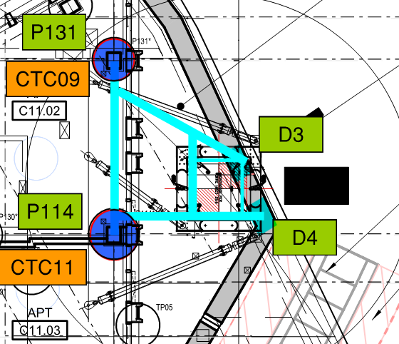
Once the basement subcontractor had been appointed (on a PCSA), they took the loads from the Crane supplier and sized the steel grillage. Now, if you imagine a 70m high free standing column, the horizontal load from wind will create a significant overturning moment. This moment along with the self weight creates large tension and compresive forces in the legs of the crane. This results in large reaction forces in the grillage supports (in this case plunge columns in piles and a diaphragm wall) and due to strict movement criteria the grillage is fabricated out of deep I Beams (large second moment of area).
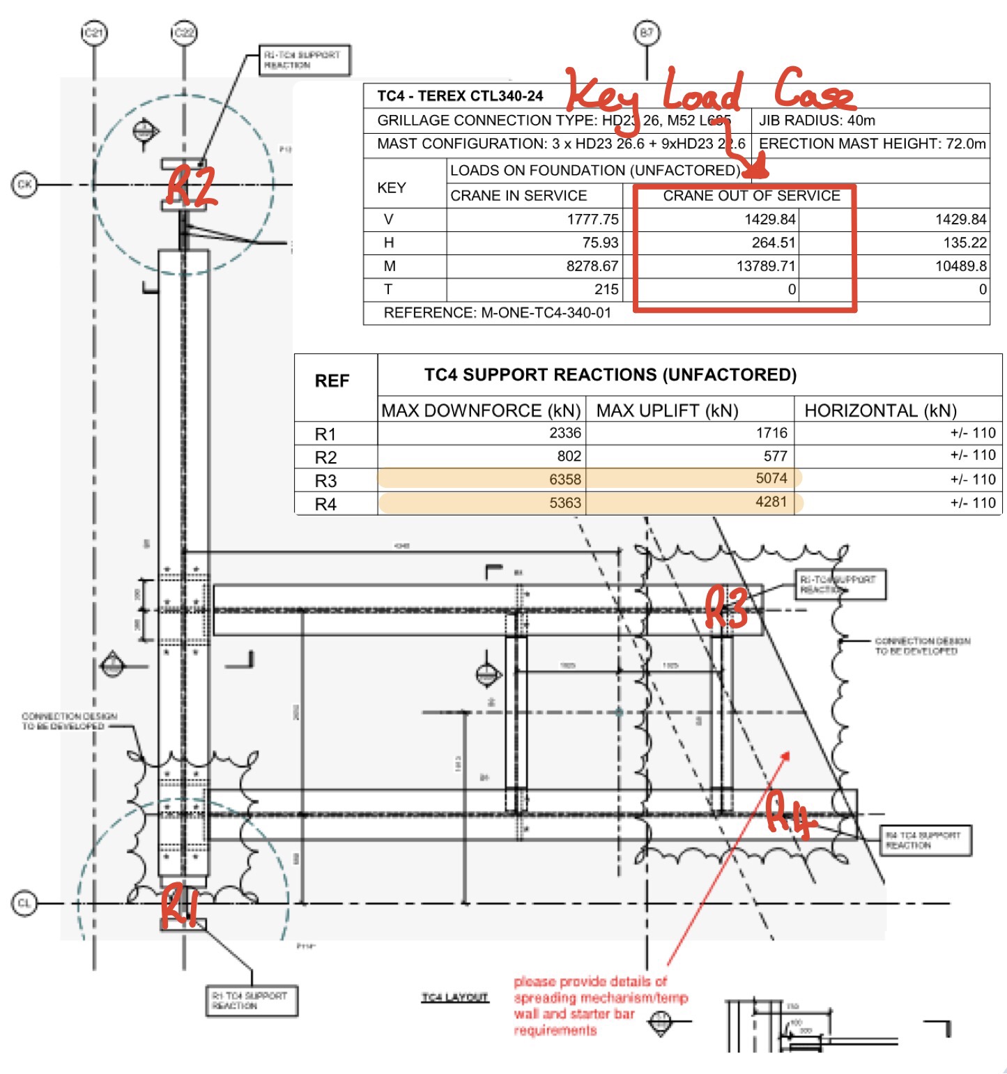 The plunge columns and piles have lots of spare capacity, provided the detail of the connection doesn’t create a load at an eccentricity and hence large moment. The D Wall however has very little spare capacity, I suspect this is because the designer has been very conservative due to the presence of a scour feature. Anyway when I went to the designer and said MPX want to put almost 13MN in two point loads on the D Wall he laughed in my face and said it’s not possible….. Que lots of head scratching by most of the MPX Engineers, calls to various people to move cranes, reduce sizes and extra piles flying in everywhere.
Anyway after a day of flapping and the drafting of a few concept ideas, a small structural firm called BG and E where emailed the concepts to have a look at. The Senior Engineer referred to the guy as an absolute ‘gun’, I assume he means he is your top third engineer. We went over for a coffee and a discussion, the first thing he said was “look at your load case, from the load envelope, Carey’s have provided the max and min for all reactions”. And here the penny dropped, its impossible to have max reaction on the D Wall at the same time, instead of text I have illustrated this below.
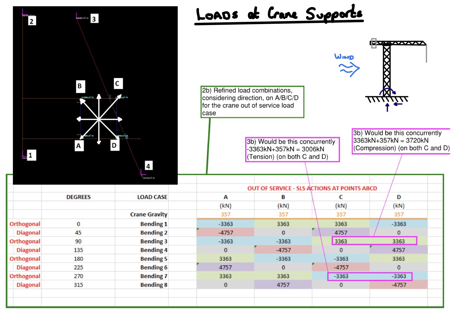
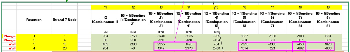
By considering the load envolpe properly the loads on the D Wall have dropped by 60% (combination 3 and 4 below), it will still be tight with the vertical capacity but potentially workable. I suppose in the long winded blog I am trying to say, always interagete loads given to you by another engineer before you plow on and use them, it saves embarrassing moments.
Reactive Dewatering
The excavation in which I am working is affected quickly by rainfall and subsequent water ingress. These wellpoints were installed as a reactive measure to lower the GWT prior to excavating to formation – the level pictured. They were only installed circa 10days ago. Does anyone know if the Corps have dewatering capability? The wells are connected to a Sykes portable pump then into a tank. Groundwater is separated from run-off (which is collected in sumps) due to potential for contamination.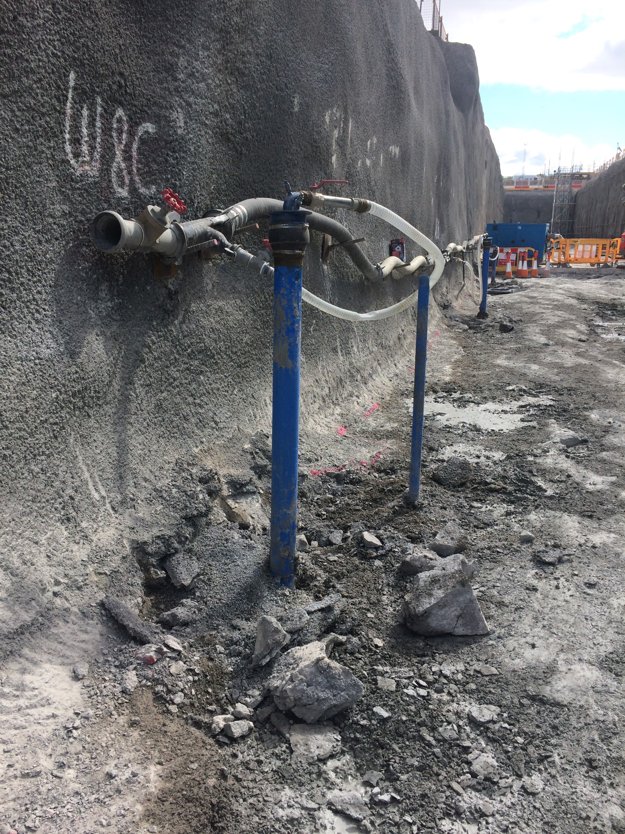
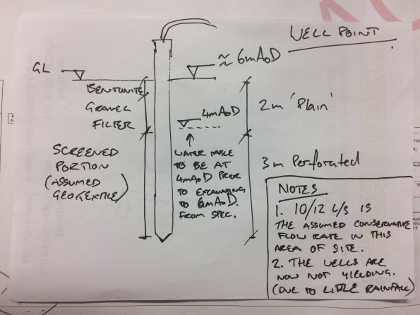
10-12 l/s is for slightly deeper wellpoints, therefore sub 10l/s is more likely.
Game of Standards
Tasked to investigate a potential cross-contamination issue within a number of disabled en-suite bathrooms, this post aims to articulate some of the issues that I came across.
Task Overview. During a scheduled visit by the Client (New South Wales (NSW) Health Care) of the Acute Services Building (ASB), it was minuted that a shower hose within one of the disabled en-suite bathrooms had the potential to make contact with the toilet basin – a cross-contamination issue. My initial task was to support a Graduate Engineer to investigate this claim.
Response to the Task. My first action was to establish the facts; what Australian Standard (AS) must installed shower hoses comply with? The Standard, AS1428.1-2009 Part 1 (Design for Access and Mobility), stipulates “that the base of the shower rail should be 700 mm above the floor, with a minimum of 1500 mm hose length”; dimensions sufficient enough for a patient to grab the hose or for a carer to wash an individual.
I then discussed the issue with the Subcontractor responsible for its installation. Of interest, and not surprisingly, the Subcontractor’s representative attempted to reassure me “that all was well” with the installations. I was not content with this level ‘assurance’ and conducted a full inspection of all 24 disabled bathrooms; 6 were confirmed as having shower hoses which could make contact with a toilet basin. (The shortest hose length to avoid contamination would have to be 1200 mm, 300 mm below the AS.)
Unable to recommend the use of a smaller hose length at this stage, and to avoid raising an unnecessary variation, I arranged a User Group meeting to establish ownership of the risk and present a solution. My initial recommendation to the Client, confident that AS 1428.1-2009 Part 1 would suffice as justification, was to implement addition disinfection measures into daily working practices to mitigate the risk of any contamination spreading. This was rebuked with another Standard, AS 3500.1:2015 Part 1 (Water Services), by the Client’s representative, which claims that “any cross-contamination potential must be mitigated”.
Mistake made: Not widening my understanding of associated Australian Standards.
The Regain. Unable to resolve the associated risk due to this AS “deadlock”, and with a young graduate stumped for options, I seized the initiative to seek advice from the Building Codes of Australia. Now furnished with an understanding of the Disability Discrimination Act (DDA) 1992, drawing attention to “it is against the law for public places to be inaccessible to people with a disability” (Australian Human Rights Commission, 2017), delineation of AS was achieved by the interpretation of a clause that states “to comply with the DDA existing places may need to be modified to be accessible, except where this would involve unjustifiable hardship”; AS 3500.1:2015 had won the argument.
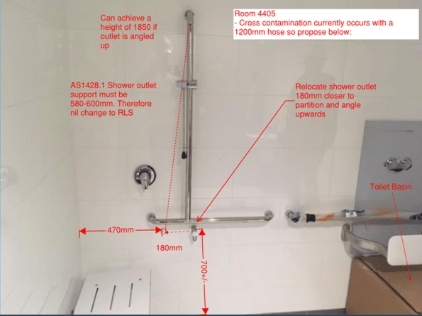
Acting on this information, I drafted a preliminary design that minimised “unjustifiable hardship” while mitigating the risk of cross-contamination; better to inconvenience the User rather than raise the risk cross-contamination across several areas of a hospital. My recommendation, illustrated below, includes relocating the shower hose rail further away from toilet basin and shortening the hose length below 1200 mm. This recommendation was upheld by MPX and the Client. A variation was then raised and a Site Instruction issued in order to complete the works.
A Quest for Answers. Understanding that one can’t foresee everything, and curious by nature, I then researched if a similar experience occurred elsewhere. It had, and in Australia! An article in the Master Plumber, Western Australia discusses that AS 1428.1-2009 is “continually being debated by installers, designers and compliance officers throughout Australia”. However, it did not provide any substantial root cause solution.
Still intrigued to find the root-cause, further investigation points towards an error by MPX’s architects. In short, they have not designed all of the disabled en-suite bathrooms large enough, despite issuing “For Construction” drawings to the Subcontractors!
Until to next time…
Static mechanical update
This is just a quick update since my last post on the projects that I have been delivering.
Hydraulic fracturing hanger – static mechanical
This project was the main focus of my last post and is nearing offshore construction. We managed to reach all the construction deliverables, a fairly simple task since it is a single discipline, static mechanical project. This was key since the asset can turnaround and refuse your construction window based upon readiness of the task. I’ve included a couple of photos below to show the location of the hanger in relation to the asset. If you look closely into the yellow box you will see the thredders bloke who has to escort the drone pilot around.


The key issues associated with offshore construction will be the removal of the heavily corroded bumper bar, contingency is the use of hydraulic jacks to persuade out of the sleeves. I’m currently luckily enough to mobilise for the days leading up to the construction but because of flights cannot stay on the platform. The offshore single point of accountability, during the construction phase, falls to the Maintenance Team Leader with daily VCs with onshore to update on progress and issues. This is particularly difficult since, unlike most of you, I cannot nip outside to go and see the problem.
Clair Low Temperature Modifications
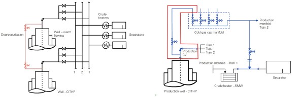
I’ve recently kicked of a new project which involves the installation of low temperature rated pipework to depressurise the wellhead following a period of shut-in. When the well is shut-in, for emergency or maintenance reasons, a gas cap forms a Closed in Tube Head Pressure (CITHP) of around 160bar (bad). If you were to depressurise this in the existing pipework the temperature would reduce to around -70degC (bad) and cause low temperature embrittlement (bad). The temporary solution, shown on the left below, was to depressurise this through flexible hoses into a known warm flowing well. This practise, while functional, was deemed unsuitable due to the requirement to break primary containment. It also took around 5 days to complete. The permanent solution, shown below on the right in blue, is to install low temperature rated pipework to depressurise, through a manifold connected to all wells, into a warm fluid downstream of the crude heater. Phase 1 of this project was completed in 2015 with Phase 2, my project, installing the pipework to tie-in 4 wells into the cold gas cap manifold. Complexities include construction priority vs asset priority, securing dates in the asset plan, while working up the engineering in a relatively short time frame.
Discipline Engineering – blast analysis
Unlike other phase 2/3 attachments, there is an opportunity at BP to conduct the phase 3 element alongside phase 2 work. As such I’ve recently started a piece of work which is to answer a technical query raised by Wood Group. This TQ queried the levels of blast, if any, which should be used when designing the new flowlines of recently drilled wells. A comparative study was conducted by Frazer-Nash which compared the methods used by 3 popular contractors used by BP. This study highlighted the lack of standardisation through interpretation of the design guidance. Frazer-Nash have subsequently conducted their own blast analysis of high risk areas of the platform which resulted in all elements of the flowlines and supports failing in both elastic and plastic tests.
My job now is to interpret the results, linking this to the Quantitative Risk Assessment, to decide what the effect of not design/designing for blast and to what level it should be accounted for. I don’t know anything about blast.
Note: Static mechanical was the term used by a structural engineer when describing his job. I think it’s an in joke.
The dangers of storing piling casings upright
Just a quick blog to warn about the dangers of storing piling casings upright, something which is done at BPS as space is tight, and I am sure is often the case elsewhere too.
When excavating down to the pile to construct pile caps, the reinforcement cage was clearly damaged on two adjacent piles, as shown in Figure 1 and Figure 2. After a brief investigation, it was concluded that the damage was probably caused by screwing a casing into the ground as indicated in Figure 3.
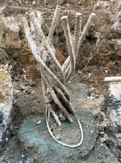
Figure 1. Damaged reinforcement cage 1.

Figure 2. Damaged reinforcement cage 2.
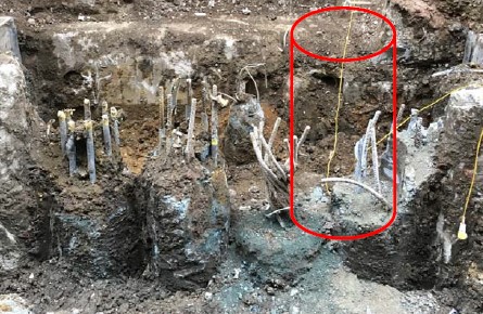
Figure 3. Assessed cause of damage.
What is going to happen now?
- Mitchellsons to break down the pile to sound steel and concrete which could be deep, attach couplers and extension bars and add additional shear reinforcing rings if required;
- Mitchellsons to then build the pile back up.
Impacts to Bauer (Piling Contractor)
- Repair and re‐work charges to be expected from Mitchellsons;
- Could cost Bauer up to £10,000 or £15,000 on this pile! There could be other piles where this has happened, not all are excavated yet.
Preventative Action
- Avoid screwing casings into the platform for storage as much as possible;
- If possible lay casings on the platform;
- If needed to store casings vertically, before screwing the casing ask the setting out engineer if the location is free of previously completed piles;
- The engineer will specifically locate clear areas and mark them out, or place casings into new pile locations to start to form the next pile.
