Archive
Alway interrogate loads!
I am currently working through packaging up the loads from the Tower Cranes, which connect to the permanent structure by a steel grillage. These loads will then be checked against pile capacities. I have been embarrassed slightly but it has taught me a valuable lesson which I will explain below.
The Tower Crane strategy on a high rise structure is a key element to a tender, the number and location is picked before sub contractors are brought on board. The tendering of packages is then conducted on this number, location and a % time allocation and are therefore relatively fixed.
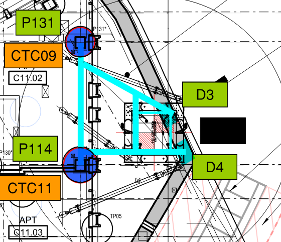
In order to be confident that the locations are feasible, MPX contracted Robert Bird Group to conduct a feasibility study which suggested a steel grillage would work in the configuration below for one of the tower cranes.
Once the basement subcontractor had been appointed (on a PCSA), they took the loads from the Crane supplier and sized the steel grillage. Now, if you imagine a 70m high free standing column, the horizontal load from wind will create a significant overturning moment. This moment along with the self weight creates large tension and compresive forces in the legs of the crane. This results in large reaction forces in the grillage supports (in this case plunge columns in piles and a diaphragm wall) and due to strict movement criteria the grillage is fabricated out of deep I Beams (large second moment of area).
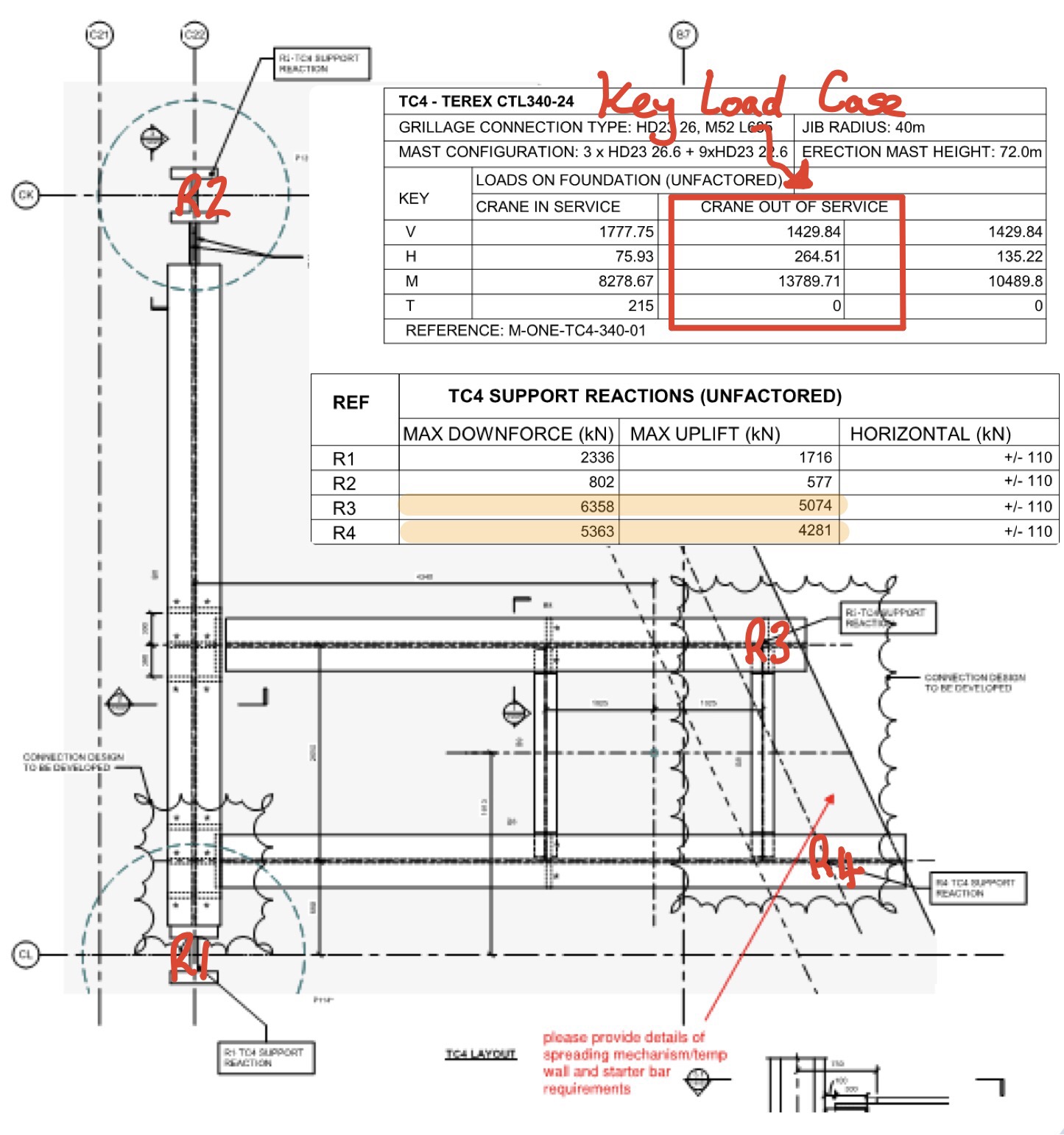 The plunge columns and piles have lots of spare capacity, provided the detail of the connection doesn’t create a load at an eccentricity and hence large moment. The D Wall however has very little spare capacity, I suspect this is because the designer has been very conservative due to the presence of a scour feature. Anyway when I went to the designer and said MPX want to put almost 13MN in two point loads on the D Wall he laughed in my face and said it’s not possible….. Que lots of head scratching by most of the MPX Engineers, calls to various people to move cranes, reduce sizes and extra piles flying in everywhere.
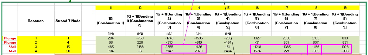
Anyway after a day of flapping and the drafting of a few concept ideas, a small structural firm called BG and E where emailed the concepts to have a look at. The Senior Engineer referred to the guy as an absolute ‘gun’, I assume he means he is your top third engineer. We went over for a coffee and a discussion, the first thing he said was “look at your load case, from the load envelope, Carey’s have provided the max and min for all reactions”. And here the penny dropped, its impossible to have max reaction on the D Wall at the same time, instead of text I have illustrated this below.
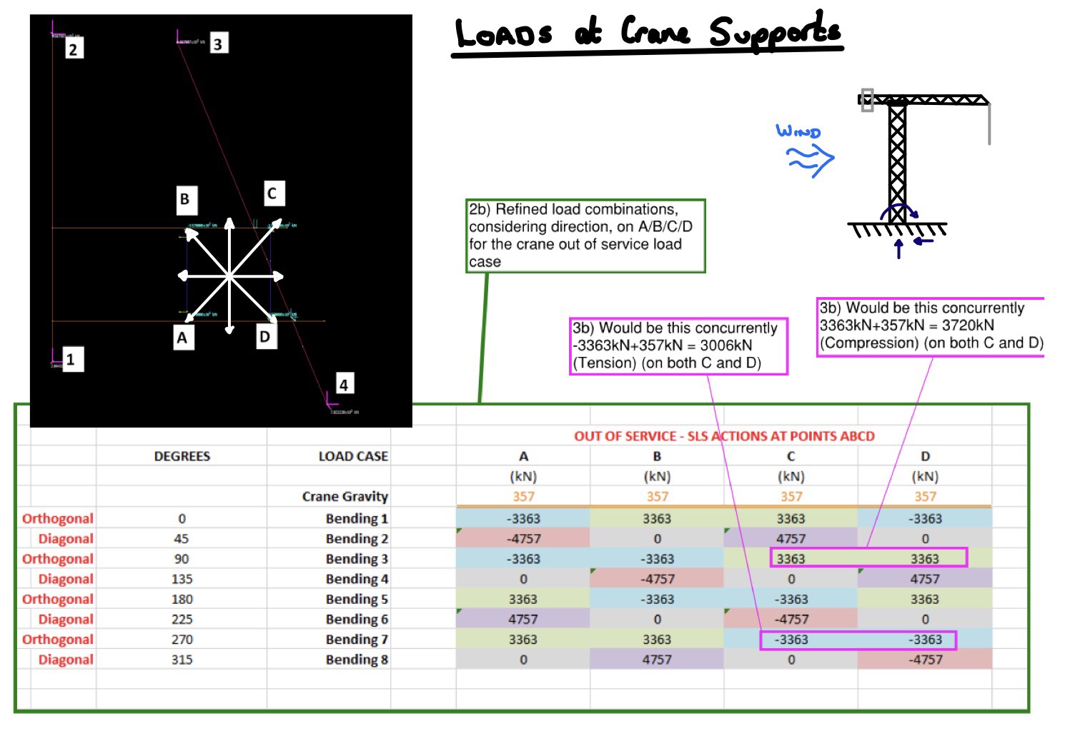
By considering the load envolpe properly the loads on the D Wall have dropped by 60% (combination 3 and 4 below), it will still be tight with the vertical capacity but potentially workable. I suppose in the long winded blog I am trying to say, always interagete loads given to you by another engineer before you plow on and use them, it saves embarrassing moments.