Backpropping puzzle
Issue. So the concrete frame sub-contractors TWD made a slight error in his backpropping calculations. Unfortunately when interrogating the structural loading document for the permanent design he forgot to subtract the selfweight of the slab and therefore overestimated the capacity of the slab in the temporary state (Figure 1).

Figure 1 – Backprop design
In the permanent design the intermediate slab is designed for a dead load of 7.4kn/m2 and an imposed load of 2.5kn/m2 (Figure 2). The dead load includes the selfweight of the slab, therefore the spare capacity of the slab at present is 2.5kn/m2 of imposed load and 0.5kn/m2 of dead load as the services are yet to be installed. Therefore, by inspection the intermediate slab is overloaded as the TWD requires 5.88kn/m2.


Figure 2 – Loading details
After a bit of research I found ‘The Temporary Works Toolkit: Part 4 – An introduction to backpropping of flat slabs‘ published in The Structural Engineer. This details how for flat slabs below 350mm a simple percentage of load transfer method can be used for calculation of loads in the slab and props (figure 3). This is the method used by the TWD in the calculations above.


Figure 3 – Method 1 for slab and prop calculation
Due to the limited capacity in the permanent case design, this method of backpropping is not acceptable.
Options. In order to solve the problem we could either change the permanent design or the TW design.
Change the permanent design. This option isn’t really possible due to the additional re-design costs and the fact the intermediate slab is 30% complete.
Transfer load to the ground bearing slab. If the backpropping is set up leg for leg with the formwork above then the load could be transferred to the ground bearing slab (Figure 4) . However, as the load is applied the props would shorten and therefore the slab will deflect and it will therefore take some load also. In order to ensure this load is not excessive could you calculate the elastic shortening of the prop and then pre-tighten the prop to minimise the intermediate slab load?
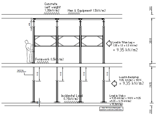
Figure 4 – Backdrop redesign
Grateful for any thoughts or observations on the logic above. Also, from others experience, is it normal that there is so little capacity in the permanent design to allow for the temporary construction state?

James, interesting blog. How was this spotted? It’s not the type of TW that would warrant a cat 2/3 check. Have you done a back calculation of the actual capacity of the slab, the excel spreadsheet from the concrete centre will do it for you. It is likely that the As,prov is larger than As,req to limit deflection and maybe crack control, so there may be a higher capacity in the slab. Look into BS8110 I think you could apply a reduced load factor as it’s TW.
Is axial shortening of the props really an issue? Surely the loads will be relatively small and more props could be used to make any shortening insignificant.
We are having similar issues with construction loads being significantly higher than the permanent case. I think it’s a common issue.
Brad,
To address your comments…
1. It was spotted due to a check requirement by Carillion TW policy. Formwork/falsework up to 3m in height is deemed to be a class B temporary works a thus requires a TW design check (See extract below in terms of classes). Note, in this case the check was conducted by Group Technical Services (GTS) a department within Carillion.
5.8.1 Class ‘A’ Temporary Works design must be carried out by a competent person and a design check carried out by GTS
5.8.2 Class ‘A+’ Temporary Works are special high risk schemes where an enhanced level of checking and inspection is required. These are likely to be rare being technically complex or where failure could have major consequences as defined in Preventing Catastrophic Events Standard
5.8.3 Class ‘B’ Temporary Works design must be carried out by a competent person and a design check carried out by a competent person who is independent of the designer.
5.8.4 Class ‘C’ Temporary Works are minor temporary works which can usually be designed based on the experience of a competent tradesperson. There is no requirement for a formal design and check.
2. Following discussion with the permanent works designer – you are correct reference As, prov compared to As, req. There is additional capacity in terms of BM and SF as As was increased to limit deflection and crack control as you highlight. However, as you can imagine, the Perm Works designer is not willing to confirm any additional capacity for the slab.
3. The axial shortening comment gives a estimate to the required pre-tightening of the props in order to transfer the load to the ground bearing slab. In reality it is only a couple of mm.
So you might not have a problem if the designers can consider the actual capacity. It is odd that Carillion haven’t just followed the BS in their TW policy with the categories.
BS5975 not 8110
Sorry I’m a bit late to this – to late in fact I suspect
As with all the TW methods there’s a lot unsaid.
Take for example temperature
The development of slab capacity is really quite sensitive to it and there might be a lot more in the slabs than the method assumes
I’ve mo wisdom on where the %’age come from but it’s got to be for a cretin job with a cretin looking after it
Here#’ what I’d do
1 Make a TMR of it
2 Set up the temporary structures in StaaDPro and play with concrete strength/stiffness to see what you actually get
3 You’re unlikely to be measuring conc temps so a maturity method is not open to you. You will have cubes and site temperature- you could guess strength and use a sq root formula for stiffness or ;look on the Conc Soc site – there’s table there
If nothing else it may cause you to question blanket tables like the one you reproduce
Oh you’ need some E for the backprop standards – should be available through the system manufacturer. My gut sense is that if the standards are embarrassed the intervening slab stiffneess will relieve it. Albeit the load distribution figures given to the slab are higher than I’d have guessed – what are the timing figures for use of the nest slab as a backpropped slab