Beams with a twist
I would appreciated peoples thoughts on the below issue I have encountered on site.
ISSUE: The steel frame erection is generally progressing well on site with approximately 90% of the steel work now erected. Unfortunately a recent site inspection highlighted that some of the secondary steel beams to level 02 had developed a twist in the member (see below). Level 03 above is a cantilevered deck which is currently temporarily supported through diagonal bracing.


The tolerances for the steel work on the project are laid down in the Structural Steel work Specification developed by Ramboll. These are in addition to the requirements of the National Structural Steel work Specification (NSSS). However, establishing the tolerances for the twist has proved more difficult than first thought. The steel contractor is currently attempting to determine a root sum squared answer from the fabrication and erection tolerances. In the meantime the visual distortion has been enough to instigate further investigation.
An as-built survey conducted by the steel work contractor confirmed the following ‘out of tolerances’ for three of the beams highlighted on site.
OPTIONS: The two options as I see it are to either leave it as it is, or to release the members and conduct remedial works as necessary. In both situations an evaluation of the significance of the twist is required to be made.
- Assess the structural significance of the twist. If not significant then do nothing and except the visual impact.
- Assess the structural significance of the twist. If not significant then do nothing, but weld a plate to the bottom flange in order to mitigate the visual impact.
- Assess the structural significance of the twist. If significant, release the connection. Relocate fin plate on primary beam to accommodate altered position of the secondary.
We are currently finding that, possibly due to the consequences, neither the structural engineers nor the steel subcontractor are willing to comment on the structural implications of the twist to the members and subsequently commit to a strategy moving forward. We are due to remove the temporary bracing in the near future. It is hoped that this along with the erection of the cladding will counteract the twist, however it is unlikely to counter it to the extent required.
It would be interesting to hear the thoughts of others with regard to the issue and potential remedial options? I would have thought that this issue must have been encountered previously through the experience of others? Any feedback is appreciated. Cheers, Al.

I believe the root cause of the twist needs to be established. Were they twisted prior to installation, perhaps in storage or transit. Or have they twisted post installation due to loading.
If it is due to loading then I would be concerned why this has happened, is it due to the temporary load state, the reliance on the bracing of the canter lever, an incorrect load case estimated for design, or incorrect fabrication of the members. Not knowing more I couldn’t comment further, but surely this is SLS/deflection failure and therefore out of specification for the steel contractor?
Henry, there were no issues with the beams prior to installation with all beams meeting the fabrication tolerances. As you suggest, this has been induced through temporary state loading. The hope is that the permanent state with the removal of the bracing will mitigate the out of tolerances observed, however it is unlikely to mitigate the level of out of tolerance seen. The designers expected some level of movement in the temporary sate, however not to the extent seen. Currently, they are waiting on removal of the bracing to see if this rebounds.
It looks like a bow more than a twist? Surely in the contract there are standard tolerances which take this into account, there is for the steel columns we are using and these are straight NSSS. Could it be that the beam is to long and has been forced into place using ratchet straps. Who does the checks before installation?
Hi Brad. We have deemed it more a twist with the top flange of the beam having not moved, being restrained by the composite slab above while it is the bottom flange only that has deflected (ack the pics may not fully illustrate this fact). I note your point about tolerances, and likewise the majority of our tolerances are taken directly from NSSS except for certain areas which require tighter tolerances on site. The fact that this is a twist means defining the tolerances is a little more complicated. I couldn’t find anything within either NSSS or the project steel spec that related to twist tolerances. Are you aware of anything different?
Here’s a few ideas
I’ve seem something like this that was caused by galv dipping – but
1 They are rolled sections so the fab should not have released anything with a lateral deformation of mores than 3mm
2 In the erection if there had been a deformation of more than that, it was the erector’s job to say so – they have only 10mm to pay with . So if they start out it’ll get worse. And if the numbers are the lateral out of vert movement there would have been significant site fabrication to get these to work.
3 I suspect (and you seem to suggest that is was OK at erection So what happened next?
a) Wriggly tin placement
b) Through deck stud welding
c) Concrete placement
There seems to obvious pattern ( ie greeter twist at the centre BUT the thing is associated with trimming beams. So if I was guessing I’d go for the through deck welding energy- but it’s a hunch
The we come to the significance
1 Get the steel tokens ( ie make sure it’s the material that it should be and that you can relay on the yield strength ( fabricator should supply – make sure it’s not some cheap low grade source
2 You have a compression face and a tensile face- get something that’s not straight and pull it-it will straighten but continue to develop tensile resistance ( ie unlike compressive elements and an initial out of straightness isn’t an absolute NO-NO
IF you were feeling ‘techhie’
1 Determine the worst twist
2 Do a theta = TL/GJ
3 Use theta to determine the shear strain
4 Use shear strain to estimate the additional implied shear stress
5 work out the works shear/direct stress combo
6 See if this embarrasses the steel by looking at a Tresca failure surface
All good nothing bad – the sort of technically based contractual cock up that’s perfect for TMR CPR
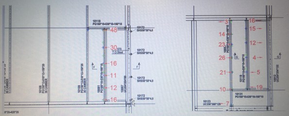
One other thing- from the GA it looks that the deformation is associated with steel around trimmed openings – but the deformations don’t look to follow a pattern
I ma assuming that the very first check was simply straightness of the upper flange ( I know it won’t be visible but go as far up the web as poss and you should be able to tell).
Errrr… over a cup of team and in the absence of most of the geometrical information I need AND assuming that the red figures are lateral movement top to bottom
I just did the calc I recommended above ( it comes down to torsional shear = rG.theta/L) and theta = delta /height of section delta = lateral movement)
Anyway I get some HIGH shears
I’d look at this if I were you
…thought I’d say