Archive
Health & Safety: The Journal Continues…
Here you have it sports fans, more snaps from my Health & Safety Journal!
That’ll do there!

Stored High in Transit (SHIT)

Do I really need to conduct a Confined Working Space Assessment?

Much Ado About Nothing?
Situation
When passing by the site offices I noticed the pulley system scaffolders had erected to speed their delivery of materials up a 12m viaduct wall, instead of using the stairs. I didn’t take a second look at first, as it looked like a routine and simple operation that they would carry out on a regular basis and “they must well know what they’re doing” it’s their specialist trade as scaffolders. However, I hadn’t previously checked their RAMS as this had been done by someone else so I was coming at this with a fresh pair of eyes.

Options
- Do nothing – it looks fine and is likely capable of lifting scaffold equipment. They must know what they’re doing.
- Question the scaffolders to get a confirmation that they are using the correct methods and that they know what they’re doing – I know they’ll tell me what I want to hear.
- Stop their works and do some checks. It just doesn’t look right.
I opted for the third one.
Issues
I used a method I recently learnt at a Multiplex 2 day quality training session I attended which included the use of fishbone diagrams for finding the root cause of nonconformities. Dubious as I was to their use, it provided another variation to a mind map. This gave me a number of routes to explore but I’m sure I will have missed elements out.

What appeared to be a simple situation can have a lot more to it as I found out:
- Work not covered in the RAMS. I checked their RAMS which had been filled out for the works to be undertaken on top of the viaduct but had not included delivery method and movements of stores. The RAMS had been checked but were not including the use of the pulley and therefore was not picked up. If it had included the lifting operation then the lifting operations coordinator would have been included in the checking of the RAMS. This means that the works shouldn’t have been carried out because they were not in accordance with the RAMS. The conformity and signing up to the use of RAMS is done by each individual at induction on site. This confirmed it was right to stop the works until the RAMS was amended and resubmitted for approval.
- Scaffold incorrectly constructed/not appropriate. What appeared to be a simple pulley mechanism was lacking moment carrying capacity. Looking at the setup I remembered portal frames and that if the load were to be transferred through 90 degrees, there would likely be a big bit of steel required at the haunch to deal with the induced moment. But surely they know what they’re doing and the scaffold connection is designed to carry the load? No – a diagonal member is required to carry the vertical load. This was not in place.
- Mechanism incorrectly fitted. After googling the pulley brand, it turned out they were using it the wrong way round and the brake wasn’t working – this made me think there was a lack of training somewhere in this mix of issues and that there could be other issues regarding the training.
- Knots. Individuals using knots to secure loads to rope must be level 1 trained. The previous item made me wonder whether this was the case and so I requested proof of their training – handily held on a CSCS card, copies of which are retained during the induction process on site. It turned out the individual was correctly qualified.
- Not valid document for pulley. The pulley itself was not provided with a test certificate. When asked to provide one there was a delay before a certificate was supplied. It came from the scaffolders’ office and is likely to have been put together following that request. However, there was no way of disproving this.

Learning Points
I consulted the HSE website, LOLER and the pulley’s operating and maintenance instructions (links supplied below), and have put together the following key points for the correct set up and use of a scaffold pulley wheel:
- The scaffold gallow bracket must be correctly erected (90 degrees with diagonal brace).
- The horizontal tube from which the pulley wheel is suspended should be fixed with right angled couplers to both the inner and outer standards.
- The Pulley wheel must have a fully functional brake (the braking action is compulsory and shall be automatic when the operating force ceases, whether the motion is lifting or lowering).
- Ropes must be the correct size to suit each type of pulley wheel (usually 18mm).
- If the rope has a hook attached for the purpose of lifting loads then it must be a safety hook, correctly spliced to the rope at point of manufacture.
- The pulley must be tested and examined before use and every 6 months thereafter (certification to this effect must be issued.)
- Weekly LOLER inspection of the wheel and rope must be undertaken by a competent person and the results recorded.
- Materials must only be attached to the rope by an appointed loader handler who is authorized, with evidence provided that they have received the necessary information, instruction and practical experience, particularly in the types of knots used to secure loads (minimum requirement must be COT course, H&S test and CISRS Trainee Part 1 Pass).
Conclusion
The most frequent causes of incidents regarding pulleys relate to the inadequate attachment of the load to the rope, the incorrect attachment of the wheel itself and a non-functioning brake. Specialist trades are assumed to know their methods of work and it is easy to think they have the definitive knowledge of a subject. However, whilst implementing their skills at the lowest level they may be using equipment they haven’t touched for some time or are unfamiliar with.
References:
CAP 609 General Information Booklet
Requirements for all “thorough examination” documents
Scaffold CIRSR training booklet and website “Construction Industry Scaffold Record Scheme”
Moment Capacity For Circular Pile Section! Any Thoughts?
During a routine inspection of pile caps prior to concrete this morning, I identified that one of the piles was offset by 216mm! At first glance it didn’t look that significant. However, the drawings highlighted a tolerance in plan of 75mm and the Mecc in the pile design was 206Knm! A Non-Conformance Report (NCR) was issued to the groundworks subcontractor immediately and they were told to assess the impact.
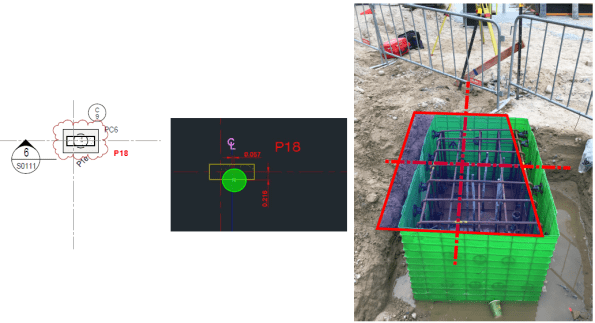
Markup used to highlight problem for NCR. Dashed line shows actual C/L for column.
This would have an impact on the pile and the pile caps, which were procured via 2 different subcontract packages with 2 different design consultants. Because of this I knew that a resolution wasn’t coming anytime soon and I wanted to complete some of my own checks.
I could see 2 potential problems with this:
- You can see in the image above that the steel fixers have just plonked the reo cage for the cap directly over the pile, which leaves the column off centre on the pile cap. This would create some bending stress in the pile cap and tension stresses may develop in the concrete = BAD. (Did quick P/A – M/Z = -0.5 N/mm2! Not sure how significant that is?)
- If the pile cap is moved back into the correct position (outlined in red above); then the pile is offset = Moment created in pile head due to eccentricity.
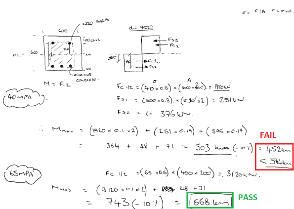
The images below show a section through the problem and some rough calculations. In summary, the moment created by the eccentricity is 594Knm and a quick strut and tie model identified a tensile force of 634KN in the top of the cap, therefore, Ast required = 1585 mm2. The current N16 @250 E.W.T.B was insufficient and I think additional steel ties will be required in the top of the pile cap. Not a showstopper.


I THEN HIT A WALL!! HOW DO YOU CALCULATE THE MOMENT CAPACITY OF A CIRCULAR SECTION?
I’m sure the answer is glaringly obvious, but I couldn’t get my head around it. As an alternative I transformed the circular section into a square section and reduced its capacity by 10%.
Whilst checking the ITPs for the CFA piles, I also identified that the concrete strength used was 65 Mpa, despite the design and construction drawings only calling for 40 Mpa. Nobody on site can recall why 65Mpa mix was used, but my calculations show that this apparent mistake could actually have increased the piles flexural capacity enough to resolve this issue!
Below are my calculations for Mmax. If anyone can provide a solution for a circular section it would be much appreciated.
Blast Analysis in the Urban Environment Lecture
Blast Analysis in the Urban Environment
The Institution of Structural Engineers is running a series of lectures, this one I think is particularly interesting, it is the penultimate one in the series.
| Date | 27 September 2017 |
| Time | 17:30 for 18:00 start |
| Venue | The Institution of Structural Engineers, 47-58 Bastwick Street, London, EC1V 3PS, UK |
| Speaker | Nick Misselbrook – Associate Principal and Office Director, Thornton Tomasetti Defence Ltd. |
Description
Protective building design requires a detailed understanding of blast loads and explosion damage mechanics. Many of the tools available for blast analysis are based upon a combination of empirical data, analytical approximations and scaling rules, which are not always accurate for explosive events in complex urban environments.This lecture will give an overview of the blast analysis tools currently available, demonstrating where and when such tools are valid, and a look at state of the art possibilities.
Speaker
Nick Misselbrook is an Associate Principal and Office Director for Thornton Tomasetti Defence Ltd. Nick has an MSc in Weapons Effects on Structures from the Royal Military College of Science, is a Chartered Engineering and Chartered Physicist and a Member of the Register of Security Engineers and Specialists.
The lecture is free and you can register at the link below.
There is also a webinar and database of previous lectures from the series.
https://www.istructe.org/techlecseries
The final lecture is on the 5 October – ‘The success and potential failure of engineering computational design’. Details can be found at the above links.
