Moment Capacity For Circular Pile Section! Any Thoughts?
During a routine inspection of pile caps prior to concrete this morning, I identified that one of the piles was offset by 216mm! At first glance it didn’t look that significant. However, the drawings highlighted a tolerance in plan of 75mm and the Mecc in the pile design was 206Knm! A Non-Conformance Report (NCR) was issued to the groundworks subcontractor immediately and they were told to assess the impact.
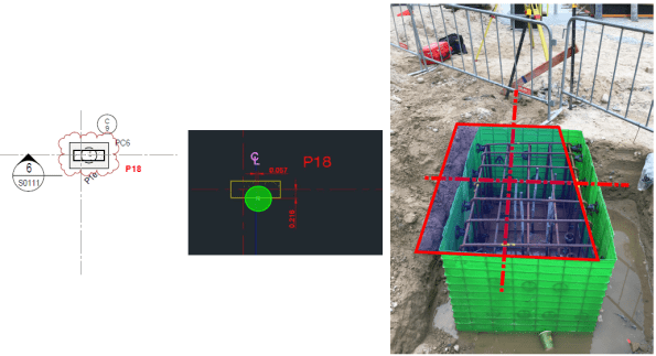
Markup used to highlight problem for NCR. Dashed line shows actual C/L for column.
This would have an impact on the pile and the pile caps, which were procured via 2 different subcontract packages with 2 different design consultants. Because of this I knew that a resolution wasn’t coming anytime soon and I wanted to complete some of my own checks.
I could see 2 potential problems with this:
- You can see in the image above that the steel fixers have just plonked the reo cage for the cap directly over the pile, which leaves the column off centre on the pile cap. This would create some bending stress in the pile cap and tension stresses may develop in the concrete = BAD. (Did quick P/A – M/Z = -0.5 N/mm2! Not sure how significant that is?)
- If the pile cap is moved back into the correct position (outlined in red above); then the pile is offset = Moment created in pile head due to eccentricity.
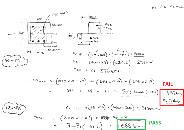
The images below show a section through the problem and some rough calculations. In summary, the moment created by the eccentricity is 594Knm and a quick strut and tie model identified a tensile force of 634KN in the top of the cap, therefore, Ast required = 1585 mm2. The current N16 @250 E.W.T.B was insufficient and I think additional steel ties will be required in the top of the pile cap. Not a showstopper.


I THEN HIT A WALL!! HOW DO YOU CALCULATE THE MOMENT CAPACITY OF A CIRCULAR SECTION?
I’m sure the answer is glaringly obvious, but I couldn’t get my head around it. As an alternative I transformed the circular section into a square section and reduced its capacity by 10%.
Whilst checking the ITPs for the CFA piles, I also identified that the concrete strength used was 65 Mpa, despite the design and construction drawings only calling for 40 Mpa. Nobody on site can recall why 65Mpa mix was used, but my calculations show that this apparent mistake could actually have increased the piles flexural capacity enough to resolve this issue!
Below are my calculations for Mmax. If anyone can provide a solution for a circular section it would be much appreciated.

Sorry I did not comment earlier
On the level of implied tensile stress- the tensile strength of uncracked concrete is about one 10th of the compressive strength ( I wobble about with the figure of 4N/mm2 )
The capacity calculation ignores the axial load. A short way is to do to the back of the Scheme Design Manual ( Concrtete Centre) IF has some interaction diagrams for stocky concrete columns
Have a look because the required reinforcement rate is about 3 times what you have!