Archive
You sunk my barge……
I thought you may like the pictures. As many of you know, at the Northern Line Extension we use barges on the Thames in order to remove our muck, fed by a conveyor system from our site.
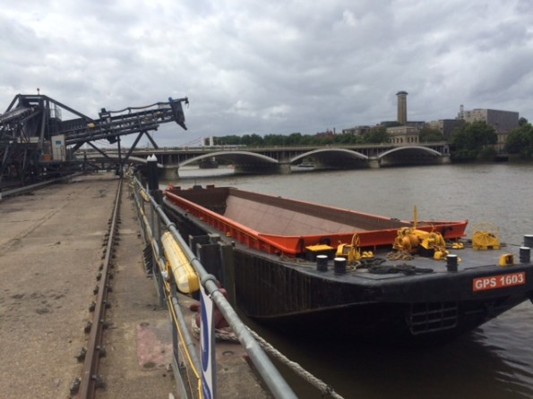
Fig 1. Empty Barge
The capacity is between 1200 and 1600t depending on which barge is being used, measured by the draught of the barge. The draught is measured prior to loading, using draught marks, and monitored during loading so that the weight in the barge is known; as a back up the weight of muck is measured as it goes over the conveyor belt.
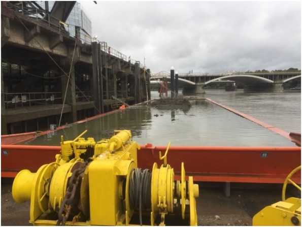
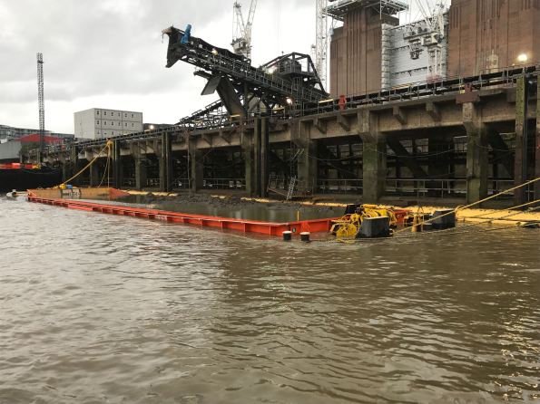
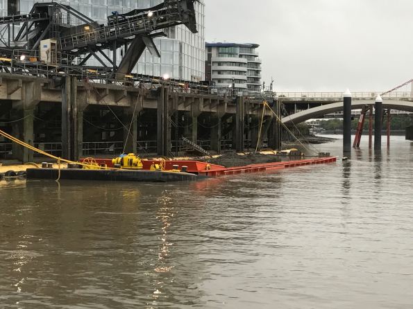
Fig 2 Sunk Barge
So what actually happened? The Lighterman who is responsible for loading the barges was carefully watching as the barge was being loaded, the draught was ok. Despite the ever increasing reading from the conveyor belt read out, the draught was still ok. Once the conveyor belt reading was in excess of 1900t the conveyor belt was stopped, but the draught was still ok……. Turns out the barge was just sat on the river bed so despite what the photos look like, technically the barge did not sink, it just failed to float once the tide came in.
Walter Reed Army Institute of Research (WRAIR)
Hello all. Just a quick update on my mechanical adventures in America. My sites at the United States Army Medical Research Institute of Infectious Diseases (USAMRIID) are drawing to a close so I was asked to head down to military Medical Research camp known as Forest Glen to fill in a gap created by their resident Mechanical Engineer retiring. Forest Glen is home to the Walter Reed Army Institute of Research (WRAIR) and is located just north of Washington D.C. The distance from home is actually smaller but with D.C. traffic (rumor has it that it is intentionally bad so as to act as a deterrence to invading forces!?!) my commute time has increased.
WRAIR is the largest biomedical research facility administered by the U.S. Department of Defense (DoD). The task at WRAIR is to repair ten air handling units (AHU), three of which are located in the basement with the other seven located on the roof in three separate “penthouses”(see image 1). These AHUs supply a variety of rooms within WRAIR including everything from animal laboratories, patient observation areas that monitor brain injury, and sleep management, photo development rooms as well as offices.

Image 1: Three Penthouses located on roof
Due to the fact that constant clean air supply is key to the operation of these rooms disruption to the AHUs has to be kept to a minimum. “Repair” is a bit of a misnomer as it is more of a full renovation of the inside of the AHUs while keeping the outside shell. For this to work correctly temporary AHUs (see image 2) are located beside each AHU prior to the beginning or work. The temporary units are then connected to the system as close to the existing AHU as possible.
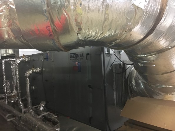
Image 2: Temporary AHU
The existing AHU is powered down at the last possible moment with the temporary AHU immediately kicking in so as to avoid disruption to the labs downstairs. To further avoid disruption this always takes place at around 0500 when no humans are in the building and the ambient temperature is naturally low.
The repair of the existing AHUs consists of effectively gutting the interior (see image 3), installing a divide in the middle so as to allow maintenance of the AHU in future without the requirement for temporary units and then replacing the filters, the copper cooling elements (see image 4), humidifier, fans and mixing chamber.
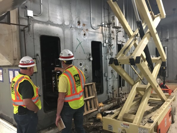
Image 3: Gutted AHU
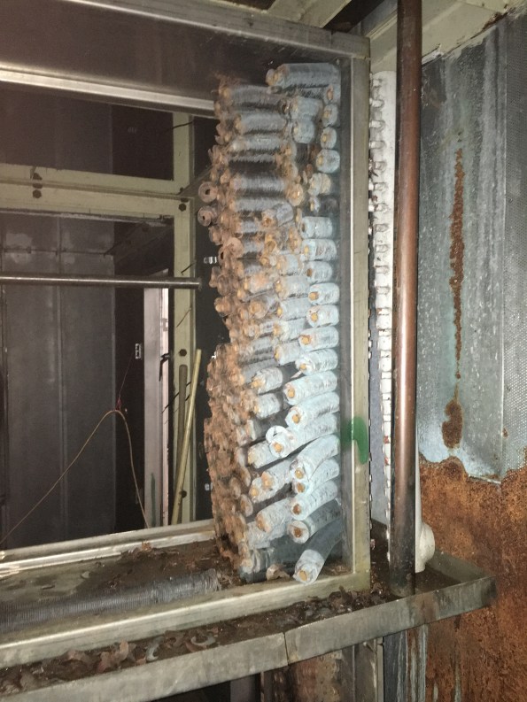
Image 4: Removed cooling coils
Currently we are on the 3rd AHU of 10 with roughly 2 months allocated to each unit. The project is currently ahead of schedule but due to the limited times the AHUs can be shut off or tested once completed any delay could easily devour the existing lead.
Cofferdam Dewatering Assistance Required
Civil friends, I would appreciate your input on the following dewatering issue I am currently faced with. This to ensure I am on the right path before I look into a suitable well point dewatering system, effects of drawdown, settlement and dealing with contaminates in the groundwater etc.
Design
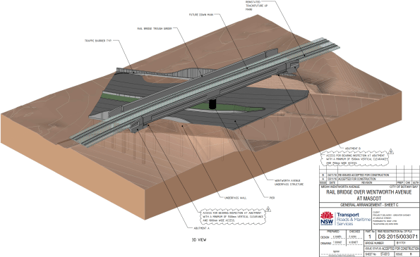
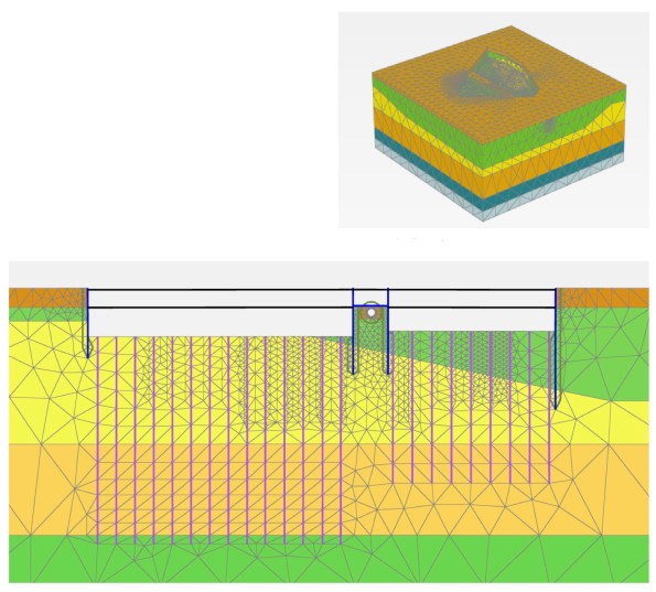
Sheet piles have been installed as temporary works to a set depth to form a single skinned cofferdam. A rail bridge will be subsequently constructed over the sheet piles footprint, prior to the cofferdams excavation to create an underpass. To date the sheet piles have been installed but there is no set solution to dewater during excavation.
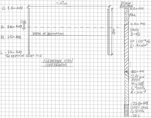
The rail bridge is at 8.5 mAHD, the sheet piles have been driven to a depth of -3.5 mAHD (12m long). To establish acceptable dry conditions for work, it has been proposed to dewater to 1.5 mAHD (the finished underpass road level is above the water table).

Conceptual Model of Groundwater Flow
There are two main groundwater systems beneath the site, a deeper confined groundwater system separated by the fractured Hawkesbury Sandstone and a shallow, unconfined / semi confined system within the Botany Sands. I have taken the groundwater level as RL 3.6 mAHD based on advice from Douglas Partners. Recharge of the Botany Sands Aquifer occurs through direct rainfall infiltration in the highly permeable sands as well as high and low tide. I have taken the average permeability across the Botany Sands as 1 x 10⁻⁴ m/s as per Douglas and Partners advice.
Estimation of Total Flowrate
I have used analytical methods to estimate the flow into the cofferdam which has produced a rather high daily flow rates of 1.9Ml per day.
Below is a draft flownet for the problem.

It has been deemed unfeasible to drive sheet piles to the clayey sand layer which may or may not be there or provide a cutoff.
Completed Rail Bridge and Underpass structure
Many thanks.
AHD – Australian Height Datum
Damage to buried pipelines
Whilst enjoying a Friday morning lull in tempo, I thought I’d produce a quick post updating everyone on a small portion of my work on the Joint Operations Centre (JOC) Project; a part of the wider East Campus program.
Work thus far has been varied with business as usual mostly focused on construction contract administration, quality control management, and project engineering. Additionally, the project’s lead engineer often gives me additional tasks which can almost be viewed as projects. The latter mostly concern issues on site that need a combination of both project management and technical understanding to resolve. As an example, one of the first tasks given to me concerned cracked valves in one of the underground pipe networks, which will be the topic of this blog post:
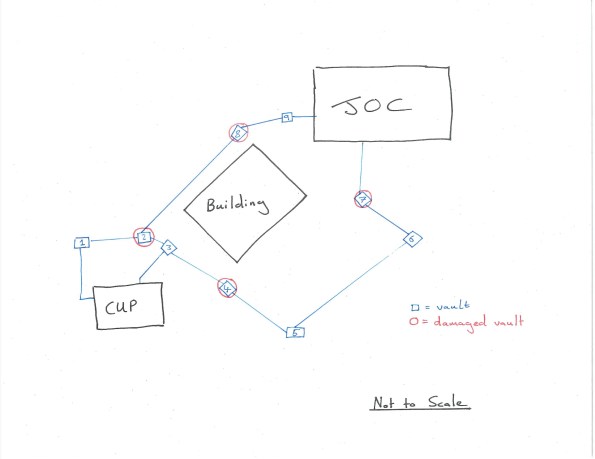
The majority of the JOC’s cooling is performed by chilling water in a separate building, the central utility plant (CUP). Chilled water is pumped from this plant to the JOC, where it is warmed at heat exchangers before returning to the CUP to repeat the cycle. The path between CUP and JOC is interspersed with mechanical vaults that allow maintenance and access to a number of valves on the underground pipe network (See hand sketch below – the blue line indicates the pipeline and includes both supply and return pipes; note the redundancy with two paths). Unfortunately, a number of valves within these vaults became damaged with large cracks appearing in the fittings. Testing of the valves confirmed the damage was to be caused by flaws in the design or fabrication of the valves. I was tasked with leading the root cause analysis and resolution of the issue.
Surveys of the damage suggested the cause lay in excessive settlement of the pipes between several mechanical vaults. By modelling the pipes as strip foundations, I was able to use Burland and Burbidge’s method to produce a ‘fag-packet’ calculation of expected settlement that corroborated this hypothesis (survey data indicated actual settlement almost 3x greater than predicted).
I was then responsible for co-ordinating numerous meetings between contractor, client, the designer of record and ourselves (USACE are the client’s representative) in order to agree a path forward. As you can imagine, nobody admitted fault and neither was anybody prepared to spend money to prove where fault actually lay. Stuck in a catch-22 situation, I was able to persuade the general contractor, Hensel Phelps (HP) into hiring a geotechnical engineer to investigate the issue. I was also able to secure financial authorization to get the designer (AECOM) to evaluate the results of my own investigations and provide recommendations. This was to also include copies of the designer’s original work, confirming the expected settlement of the pipe under assumed loading. This report, after a number of returns due to missing information, finally arrived yesterday. AECOM’s design used the modified Iowa formula – a well-recognized method of calculating displacement in laterally loaded “flexible” pipes (I must admit, one of the surprising revelations during my analysis was the fact such large steel pipes are considered flexible). The difference between using my Burland and Burbidge method and the modified Iowa formula was my results suggesting 50% more settlement (3/8 inch compared to ¼ inch). However, this may have also been caused by AECOM’s grillage analysis and subsequent live loading on the pipe being slightly less than my own.
On site, HP, has already completed replacement of damaged pipe sections. They have also performed additional remedial work within the vaults by unbolting undamaged connections, allowing free ends to deflect and reconnecting with specially fabricated ‘offsets’. On the basis that the soil is coarse grained (so long term settlement is less of a concern) and the stresses from settlement have been released through the disconnection program, it is “hoped” that the issue has therefore been resolved.
Presently, the plan is to attach strain gages to the newly connected sections and monitor for future settlement; my work to confirm what happens (and who pays) if the strain goes beyond the agreed threshold continues. The contractor is only liable for damages and the costs of repair and replacement for a year after final acceptance – after which, the costs sits with the government who would then need to prove fault and take legal action to cover damages from either the contractor or designer.
The whole experience has taught me a lot about the contractual relationships within both construction and also large government projects. It’s also developed my management skills in terms of co-ordinating multi-disciplinary and stakeholder meetings (in this instance mostly mechanical engineers are involved as it concerns their feature of work, but I’m also getting a lot of exposure to electrical and commissioning engineers in another of my roles).
Finally, I’ve noticed that I’m far more understanding of the general contractor’s stance during periods of conflict compared to USACE management, who are often very untrusting; I put this down to my relative independence compared to the rest of the team here but I suppose it could also be a result of something personal, cultural, or my military background. Has anybody else observed something similar or different on their projects?
Finally, a teaser for anybody on phase 1 currently considering the USA as your attachment location. the rendering below shows the initial architectural concept for the East Campus program (It’s one of the few images of work that are releasable – The JOC and its large rounded roof is on the far left of the picture). There will be work here for at least another decade with multiple opportunities to cover several projects simultaneously, all at different stages of construction. If you’re interested and would like to know more (both civil and E&M), just get in touch!

The Rising Factory
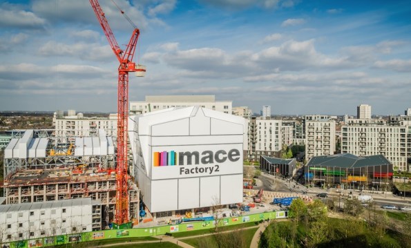
Figure 1. East Village, Stratford.
Summary
As part of the handover between Skanska and Mace, all Battersea phase 2 staff are getting various presentations from Mace to tempt us to join them. Yesterday we had a presentation which featured a different Mace project, East Village in London, which is being constructed in a really innovative way, and I thought I would share. I must stress that I have not worked on, visited (I am trying to arrange this) or even seen this site, and that my knowledge is restricted to what is contained in here. They are using jump forming of sorts, but instead of just producing a concrete core, they are raising the ‘rising factory’ to reveal a completed floor of the building. Interestingly, all lifting is done via gantry cranes inside the rising factory, utilising the riser shafts within the building. This negates the need for tower cranes (NB the tower crane in Figure 1 is for the surrounding construction) and eliminates down time due to high wind. The weatherproof factory environment also allows for safer construction year round.
Background
The jump form and slip form systems are well established, but what emerges is the raw core of a building with all the remaining elements still to be constructed, with all the associated programme disadvantages. The ‘rising factory’ is a 10 storey high enclosure inside which the construction of a complete multi-storey building takes place over 5 construction levels. What emerges as the factory is jacked up on its weekly cycle is a level of newly constructed building which from the outside is complete and just requires finishes to be applied internally. Cranes (including vehicle container offloading), storage and welfare facilities needed for the construction activities are all within the enclosure and varying types of activities happen at each level from construction of the structural columns and slabs at the top to completion and sealing of the cladding at the lowest level. A jacking system is permanently attached to the factory columns and the jacks engage with the support brackets when the factory makes its weekly lift. The factory facilitates the construction of a 30-storey building with a cycle of a week per floor, giving large programme and site health and safety benefits. These benefits are significant for all parties.
Operation
In 2016 Dorman Long Technology (DLT) were awarded the contract by Mace to supply two pinned climbing jack systems for the construction of twin residential towers at their East Village Development. The project aims to construct two high-rise residential towers using pre-cast concrete construction. The ‘rising factory’ concept is used to create a waterproof factory environment for construction and fit out of each floor. The scheme uses a temporary steel rising factory building erected over the top of each residential tower during construction, which contains two 15t gantry cranes. After each floor has been constructed the temporary steel rising factory is lifted by 3.3m by the 4 x DL-CP250 pinned climbing jacks which remain static, but lifts the climbing bar connected to the rising factory, allowing the next floor to be built.
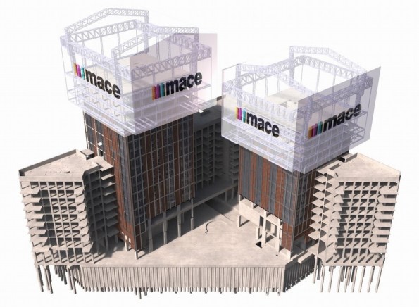
Figure 2. Image from 4D modelling.
The first jump of the rising factory was completed successfully in Feb 2017. During this jump the factory was raised 6.6m – twice the intended standard jump distance of 3.3m. This was to allow completion of assembly & cladding of the factory structure and construction of the next two floors of the 30 storey tower. Figure 3 and Figure 4 show the factory before and after the jump. The factory, which in this partial completed state weighed 565t, was lifted using four 250t DL-CP250 pinned climbing jacks controlled by DL-P40 computer control system, as shown in Figure 5.

Figure 3. Tower before jump.

Figure 4. Tower after jump.
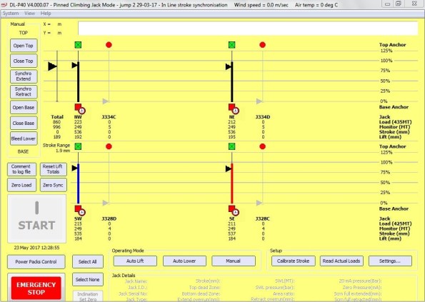
Figure 5. DL-P40 computer control system during jump
During construction of towers, the weight of the rising factory is supported by four hydraulically operated pins (Figure 7) which connect it to the high-rise building via four jump brackets, one fitted to each corner column of the building. All vertical and horizontal loads from the rising factory are transferred to the building via these pins. During factory operation the pinned climbing jacks (Figure 6) and climbing bars are not subjected to any imposed loads. During the jacking of the factory the pins are hydraulically withdrawn and the pinned climbing jacks lift the climbing bars which are fitted to the rising factory. The pinned climbing jacks are each mounted on top of a jump bracket via a pair of link plates.

Figure 6. DL-CP250 Pinned Climbing Jack.

Figure 7. Hydraulically operated pin.
Conclusions
This method appears to offer huge benefits to construction, but like many innovative techniques, it must be chosen early in the design stage. The footprint of the building must not be too big, and the risers must be sufficiently large and appropriately placed to allow all of the required materials to be lifted through them. Although this case study uses pre-cast concrete elements (saving further time) I cannot see why it could not be adapted to contain a concrete pump and use cast-in-situ construction if desired. The benefits are obvious, and although there are numerous projects where this construction method will not be suitable, I expect to see an increase in the use of rising factories.
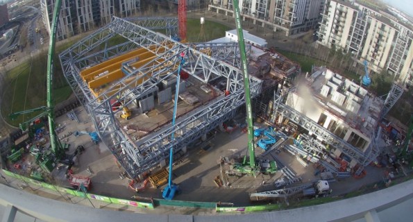
Figure 8. The rising factory from above.
A Forgotten Post: Almost a Civil Engineer…?
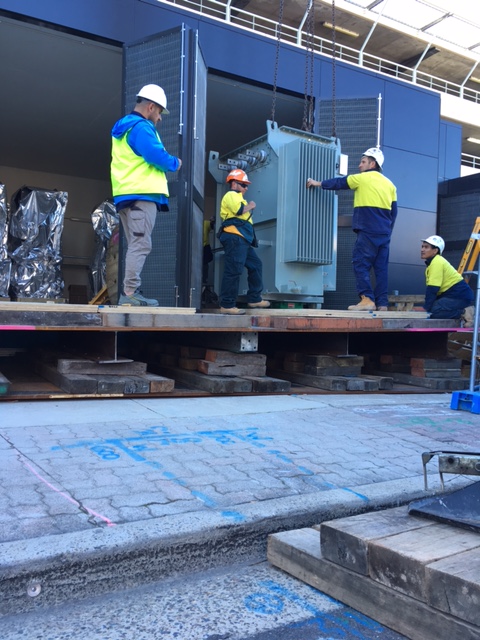
Task Overview. Part of the Substation Scope of Works was the installation of two 1500 kVA transformers, both weighing 5000 kg.
Expedient Engineering Opportunity. Initially functioning as a supervisor to the wider-Substation construction, it was during a routine meeting that I noticed no detailed plan existed to safely install the transformers. The original idea to lower transformers into the Substation had overlooked that the roof and doors to the structure were installed early. (At the time, the Project Manager thought this was a “quick win”.)
I resolved this issue by devising a plan to design and construct a temporary platform in order to safely install the transformers. Realising my very limited Civil Engineering competency, I engaged with an approved subcontractor – Shore Hire – to develop my concept into a legally recognisable design, should something go wrong; I achieved assurance by requesting a design certification from Shore Hire’s engineers.
Pictures: (Top to Bottom) Initial proposal; detailed design from Subcontractor; design constructed; and, transformer being released from the crane and wheeled into position.


Until next time…
BP – pipe support loads
Alongside project delivery I am currently working as part of the mechanical discipline engineering team. The work I am doing for them is answering Design Technical Queries (DTQ) and Engineering Queries. I started trying to explain both but it became too wordy, the DTQ is explained below:
A DTQ was submitted in relation to the pipe support loads experienced during a blast event along new production flowlines that are due to be installed (some have actually already been installed). The Clair platform has legacy issues relating to blast whereby the original platform design was never designed for blast. As such, all current in-use flowlines and pre-invested (installed but not hooked up) are supported using standard U-bolt pipe supports. The U-bolts are not designed to be able to withstand a blast event since the primary load path for the bolts is vertical. The U-bolt manufacturer only specifies a max vertical load therefore a max lateral load must be assumed.
Wood Group are the contractor designing the new flowlines (to be tied into pre-invested) and are concerned that in the event of a blast a number of the pipe supports will fail due to excessive lateral loads. Their basis for this statement is a rule of thumb that the max lateral load is a nominal 30% of the max vertical load. The manufacturer stated max vertical load is based upon the yield stress of the material. They have asked if they are to replace all the pipe supports since they all fail.
Recognising there are platform wide issues relating to blast, Fraser-Nash Consultants (F-N) were contracted to conduct targeted blast analysis on a complete flowline (one designed IAW original platform design). By modelling the U-bolt failure load using a similar method as Wood Group, F-N came to the same conclusion that the lateral loads are excessive. In order to understand the actual post-yield material characteristics (ie strain hardening etc.), a nonlinear analysis was conducted based upon the U-bolt geometry and material. From this they were able to establish a plastic collapse load. When modelled in this manner all the U-bolts were found to remain within the plastic collapse load. The picture I’ve attached kind of explains this problem through the stress-strain graph.


My response to the DTQ was initially to accept the F-N analysis since the U-bolts do not collapse fully, maintaining some structural integrity. My justification for this was that the design event is blast, a one-off whereby the performance criteria is to maintain primary containment. No-one seems content with this response and I am now stuck trying to provide more justification, any ideas?
One Nine Elms
Hi All, It’s a long one with few pictures, but interesting……. I think.
A recent series of events on One Nine Elms has left me wondering why project managers get paid ‘the big bucks’.
A new project manager has recently started in the project team, he previously worked on the project for McGees before joining Multiplex about 2 years ago. As such he has a good understanding of the project with exception of the sewer complications. Anyway he has arrived to impress the two project directors, with his current mantra being progress at all costs, which has potentially had some significant cost implications for Multiplex.
The diaphragm wall has been constructed under a design and build contract by Balfour Beatty Ground Engineer (BBGE), who Is contracted directly to the client. The first main contractor, CI- ONE, had a traditional bottom up sequence with props below or above the permanent basement slabs. This is what the wall was originally designed and partly constructed for. Balfour Beatty then became the main contractor (on a PCSA), and they changed the methodology to top down. This different sequence was re-checked against the as built wall, with BBGE confirming the design was sufficient. When Balfour Beatty and the client were unable to agree on cost and programme, Multiplex won the subsequent re-tender on a semi-top methodology which I have mentioned in a previous blog. Crucially as MPX did not signed the head contract until July and potentially not doing an in depth review of the project risks, they recommended to the client that the new sequence be checked again, instead of spending the c£40k themselves. As a result this check only started about 6 weeks ago despite Multiplex starting on site in January.
In the meantime, Multiplex have tendered, appointed and started on site the basement box subcontractor. As a result there is significant pressure to justify the subcontractors preliminaries and see some progress, i.e. Excavation to B1 formation. Armed with the fact that AKT (structural designers) had conducted a study confirming the D Wall could cantilever from B1, the new project manager actively encouraged the basement package manager to commence excavation. At this point both the project engineer and I advised that this was unwise, BBGE had not yet ‘approved’ the new sequence and there was no deflection monitoring in place. The Project and Package Manager came back with AKT have approved the sequence and an interim monitoring package has been signed with ITM. When I said that BBGE will not give warranty on their work (c£35M) if excavation commences without the approval of the sequence, I was told not to worry about the contractual stuff.
The week before the excavation started, BBGE returned the calculations for section of Wall where excavation was planned to start. The calculations showed the wall was acceptable under ULS but not SLS. The retained soil has high sulphate content, therefore the concrete exposure class is XC3, which has a. crack width limit of 0.3mm. The new sequence SLS moments cause cracks which exceeded this (theoretically), therefore the new sequence is not acceptable to BBGE. This was known before excavation and a number of things are currently being looked at to get this cracking issue to be acceptable. Interestingly during the first sequence change, BBGE could not get the deflections within limits in their WALLAP calculations. As a result AKT modelled the basement in 3D FE and have taken responsibility for deflections, slightly worryingly BBGE deflections are an order of magnitude higher.
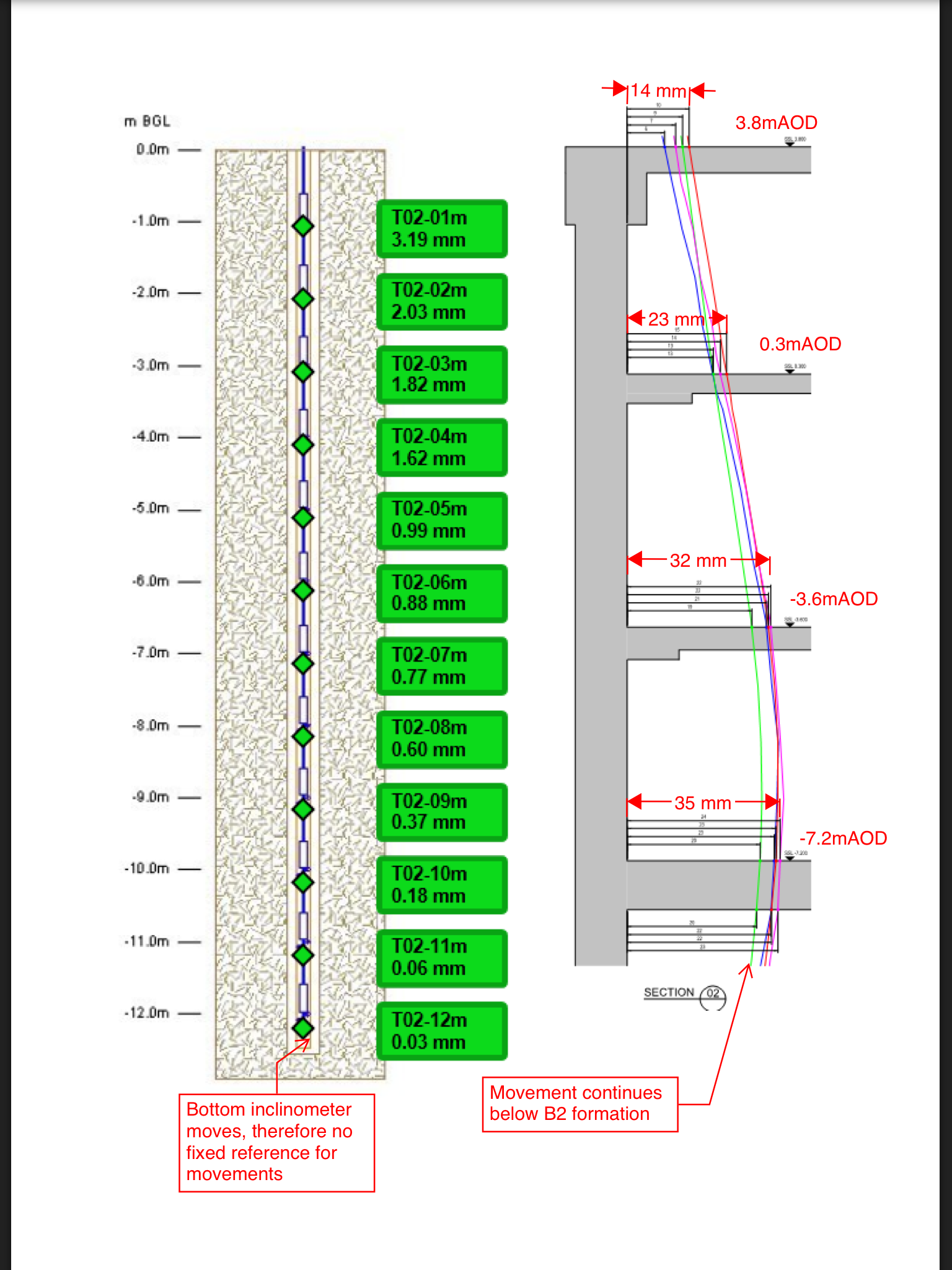
Despite this excavation commenced, with active encouragement from the project manager and construction director. With this in mind, the last thing you would want is a poor monitoring package. By chance I was asked to chair ITMs (monitoring company) pre-start meeting on behalf of the package manager, who had effectively tendered the package. It quickly became apparent that the inclinometers are not fit for purpose. They only went to B2 formation level where there would still be significant movement. This means the head of the inclinometer would need surveying manually in order to provide a reference point to baseline the inclinometer, not good for an automatic system to rely on the manual input of data to work. Furthermore it would appear that this manual reading had only been bought to be conducted once a week.
So, Multiplex have basically started excavation without approval from the designer and without any deflection monitoring in place. Low and behold, the client receives a letter from BBGE, informing them that they cannot offer warranties on their works because Multiplex have excavated not to the approved sequence and with no monitoring. The project manager and construction direction then hit the roof and basically blame the package manager, conveniently forgetting their encouragement to start excavation.
The result of this is not yet known. The two individuals had been given sound advice which they chose to ignore, they then tried to blame everyone but themselves. Poor management, decision making and leadership from individuals paid a lot to do this well.
Fellow Multiplexers don’t show this to anyone in the company.
