Archive
The Rising Factory
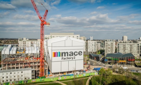
Figure 1. East Village, Stratford.
Summary
As part of the handover between Skanska and Mace, all Battersea phase 2 staff are getting various presentations from Mace to tempt us to join them. Yesterday we had a presentation which featured a different Mace project, East Village in London, which is being constructed in a really innovative way, and I thought I would share. I must stress that I have not worked on, visited (I am trying to arrange this) or even seen this site, and that my knowledge is restricted to what is contained in here. They are using jump forming of sorts, but instead of just producing a concrete core, they are raising the ‘rising factory’ to reveal a completed floor of the building. Interestingly, all lifting is done via gantry cranes inside the rising factory, utilising the riser shafts within the building. This negates the need for tower cranes (NB the tower crane in Figure 1 is for the surrounding construction) and eliminates down time due to high wind. The weatherproof factory environment also allows for safer construction year round.
Background
The jump form and slip form systems are well established, but what emerges is the raw core of a building with all the remaining elements still to be constructed, with all the associated programme disadvantages. The ‘rising factory’ is a 10 storey high enclosure inside which the construction of a complete multi-storey building takes place over 5 construction levels. What emerges as the factory is jacked up on its weekly cycle is a level of newly constructed building which from the outside is complete and just requires finishes to be applied internally. Cranes (including vehicle container offloading), storage and welfare facilities needed for the construction activities are all within the enclosure and varying types of activities happen at each level from construction of the structural columns and slabs at the top to completion and sealing of the cladding at the lowest level. A jacking system is permanently attached to the factory columns and the jacks engage with the support brackets when the factory makes its weekly lift. The factory facilitates the construction of a 30-storey building with a cycle of a week per floor, giving large programme and site health and safety benefits. These benefits are significant for all parties.
Operation
In 2016 Dorman Long Technology (DLT) were awarded the contract by Mace to supply two pinned climbing jack systems for the construction of twin residential towers at their East Village Development. The project aims to construct two high-rise residential towers using pre-cast concrete construction. The ‘rising factory’ concept is used to create a waterproof factory environment for construction and fit out of each floor. The scheme uses a temporary steel rising factory building erected over the top of each residential tower during construction, which contains two 15t gantry cranes. After each floor has been constructed the temporary steel rising factory is lifted by 3.3m by the 4 x DL-CP250 pinned climbing jacks which remain static, but lifts the climbing bar connected to the rising factory, allowing the next floor to be built.
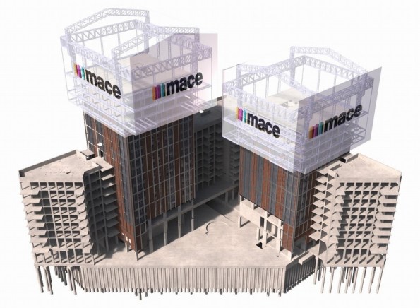
Figure 2. Image from 4D modelling.
The first jump of the rising factory was completed successfully in Feb 2017. During this jump the factory was raised 6.6m – twice the intended standard jump distance of 3.3m. This was to allow completion of assembly & cladding of the factory structure and construction of the next two floors of the 30 storey tower. Figure 3 and Figure 4 show the factory before and after the jump. The factory, which in this partial completed state weighed 565t, was lifted using four 250t DL-CP250 pinned climbing jacks controlled by DL-P40 computer control system, as shown in Figure 5.

Figure 3. Tower before jump.

Figure 4. Tower after jump.
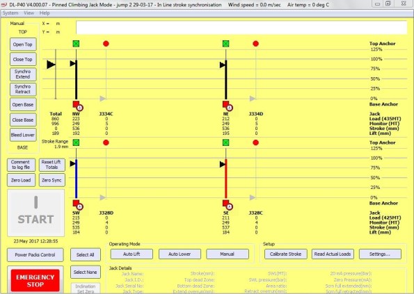
Figure 5. DL-P40 computer control system during jump
During construction of towers, the weight of the rising factory is supported by four hydraulically operated pins (Figure 7) which connect it to the high-rise building via four jump brackets, one fitted to each corner column of the building. All vertical and horizontal loads from the rising factory are transferred to the building via these pins. During factory operation the pinned climbing jacks (Figure 6) and climbing bars are not subjected to any imposed loads. During the jacking of the factory the pins are hydraulically withdrawn and the pinned climbing jacks lift the climbing bars which are fitted to the rising factory. The pinned climbing jacks are each mounted on top of a jump bracket via a pair of link plates.

Figure 6. DL-CP250 Pinned Climbing Jack.

Figure 7. Hydraulically operated pin.
Conclusions
This method appears to offer huge benefits to construction, but like many innovative techniques, it must be chosen early in the design stage. The footprint of the building must not be too big, and the risers must be sufficiently large and appropriately placed to allow all of the required materials to be lifted through them. Although this case study uses pre-cast concrete elements (saving further time) I cannot see why it could not be adapted to contain a concrete pump and use cast-in-situ construction if desired. The benefits are obvious, and although there are numerous projects where this construction method will not be suitable, I expect to see an increase in the use of rising factories.
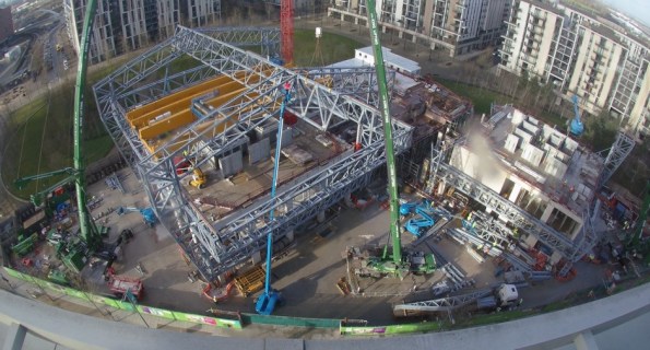
Figure 8. The rising factory from above.
A Forgotten Post: Almost a Civil Engineer…?
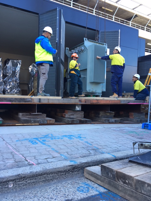
Task Overview. Part of the Substation Scope of Works was the installation of two 1500 kVA transformers, both weighing 5000 kg.
Expedient Engineering Opportunity. Initially functioning as a supervisor to the wider-Substation construction, it was during a routine meeting that I noticed no detailed plan existed to safely install the transformers. The original idea to lower transformers into the Substation had overlooked that the roof and doors to the structure were installed early. (At the time, the Project Manager thought this was a “quick win”.)
I resolved this issue by devising a plan to design and construct a temporary platform in order to safely install the transformers. Realising my very limited Civil Engineering competency, I engaged with an approved subcontractor – Shore Hire – to develop my concept into a legally recognisable design, should something go wrong; I achieved assurance by requesting a design certification from Shore Hire’s engineers.
Pictures: (Top to Bottom) Initial proposal; detailed design from Subcontractor; design constructed; and, transformer being released from the crane and wheeled into position.


Until next time…
