Archive
Damage to buried pipelines
Whilst enjoying a Friday morning lull in tempo, I thought I’d produce a quick post updating everyone on a small portion of my work on the Joint Operations Centre (JOC) Project; a part of the wider East Campus program.
Work thus far has been varied with business as usual mostly focused on construction contract administration, quality control management, and project engineering. Additionally, the project’s lead engineer often gives me additional tasks which can almost be viewed as projects. The latter mostly concern issues on site that need a combination of both project management and technical understanding to resolve. As an example, one of the first tasks given to me concerned cracked valves in one of the underground pipe networks, which will be the topic of this blog post:
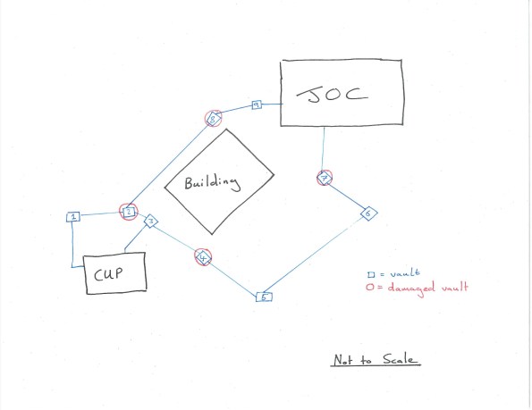
The majority of the JOC’s cooling is performed by chilling water in a separate building, the central utility plant (CUP). Chilled water is pumped from this plant to the JOC, where it is warmed at heat exchangers before returning to the CUP to repeat the cycle. The path between CUP and JOC is interspersed with mechanical vaults that allow maintenance and access to a number of valves on the underground pipe network (See hand sketch below – the blue line indicates the pipeline and includes both supply and return pipes; note the redundancy with two paths). Unfortunately, a number of valves within these vaults became damaged with large cracks appearing in the fittings. Testing of the valves confirmed the damage was to be caused by flaws in the design or fabrication of the valves. I was tasked with leading the root cause analysis and resolution of the issue.
Surveys of the damage suggested the cause lay in excessive settlement of the pipes between several mechanical vaults. By modelling the pipes as strip foundations, I was able to use Burland and Burbidge’s method to produce a ‘fag-packet’ calculation of expected settlement that corroborated this hypothesis (survey data indicated actual settlement almost 3x greater than predicted).
I was then responsible for co-ordinating numerous meetings between contractor, client, the designer of record and ourselves (USACE are the client’s representative) in order to agree a path forward. As you can imagine, nobody admitted fault and neither was anybody prepared to spend money to prove where fault actually lay. Stuck in a catch-22 situation, I was able to persuade the general contractor, Hensel Phelps (HP) into hiring a geotechnical engineer to investigate the issue. I was also able to secure financial authorization to get the designer (AECOM) to evaluate the results of my own investigations and provide recommendations. This was to also include copies of the designer’s original work, confirming the expected settlement of the pipe under assumed loading. This report, after a number of returns due to missing information, finally arrived yesterday. AECOM’s design used the modified Iowa formula – a well-recognized method of calculating displacement in laterally loaded “flexible” pipes (I must admit, one of the surprising revelations during my analysis was the fact such large steel pipes are considered flexible). The difference between using my Burland and Burbidge method and the modified Iowa formula was my results suggesting 50% more settlement (3/8 inch compared to ¼ inch). However, this may have also been caused by AECOM’s grillage analysis and subsequent live loading on the pipe being slightly less than my own.
On site, HP, has already completed replacement of damaged pipe sections. They have also performed additional remedial work within the vaults by unbolting undamaged connections, allowing free ends to deflect and reconnecting with specially fabricated ‘offsets’. On the basis that the soil is coarse grained (so long term settlement is less of a concern) and the stresses from settlement have been released through the disconnection program, it is “hoped” that the issue has therefore been resolved.
Presently, the plan is to attach strain gages to the newly connected sections and monitor for future settlement; my work to confirm what happens (and who pays) if the strain goes beyond the agreed threshold continues. The contractor is only liable for damages and the costs of repair and replacement for a year after final acceptance – after which, the costs sits with the government who would then need to prove fault and take legal action to cover damages from either the contractor or designer.
The whole experience has taught me a lot about the contractual relationships within both construction and also large government projects. It’s also developed my management skills in terms of co-ordinating multi-disciplinary and stakeholder meetings (in this instance mostly mechanical engineers are involved as it concerns their feature of work, but I’m also getting a lot of exposure to electrical and commissioning engineers in another of my roles).
Finally, I’ve noticed that I’m far more understanding of the general contractor’s stance during periods of conflict compared to USACE management, who are often very untrusting; I put this down to my relative independence compared to the rest of the team here but I suppose it could also be a result of something personal, cultural, or my military background. Has anybody else observed something similar or different on their projects?
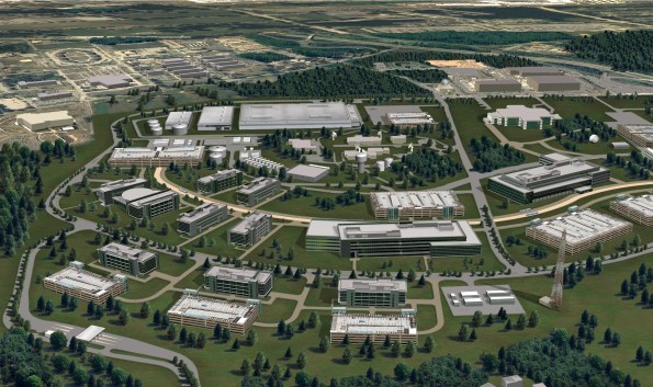
Finally, a teaser for anybody on phase 1 currently considering the USA as your attachment location. the rendering below shows the initial architectural concept for the East Campus program (It’s one of the few images of work that are releasable – The JOC and its large rounded roof is on the far left of the picture). There will be work here for at least another decade with multiple opportunities to cover several projects simultaneously, all at different stages of construction. If you’re interested and would like to know more (both civil and E&M), just get in touch!