Cofferdam Dewatering Assistance Required
Civil friends, I would appreciate your input on the following dewatering issue I am currently faced with. This to ensure I am on the right path before I look into a suitable well point dewatering system, effects of drawdown, settlement and dealing with contaminates in the groundwater etc.
Design
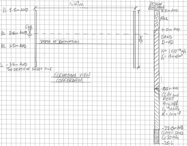
Sheet piles have been installed as temporary works to a set depth to form a single skinned cofferdam. A rail bridge will be subsequently constructed over the sheet piles footprint, prior to the cofferdams excavation to create an underpass. To date the sheet piles have been installed but there is no set solution to dewater during excavation.
The rail bridge is at 8.5 mAHD, the sheet piles have been driven to a depth of -3.5 mAHD (12m long). To establish acceptable dry conditions for work, it has been proposed to dewater to 1.5 mAHD (the finished underpass road level is above the water table).

Conceptual Model of Groundwater Flow
There are two main groundwater systems beneath the site, a deeper confined groundwater system separated by the fractured Hawkesbury Sandstone and a shallow, unconfined / semi confined system within the Botany Sands. I have taken the groundwater level as RL 3.6 mAHD based on advice from Douglas Partners. Recharge of the Botany Sands Aquifer occurs through direct rainfall infiltration in the highly permeable sands as well as high and low tide. I have taken the average permeability across the Botany Sands as 1 x 10⁻⁴ m/s as per Douglas and Partners advice.
Estimation of Total Flowrate
I have used analytical methods to estimate the flow into the cofferdam which has produced a rather high daily flow rates of 1.9Ml per day.
Below is a draft flownet for the problem.

It has been deemed unfeasible to drive sheet piles to the clayey sand layer which may or may not be there or provide a cutoff.
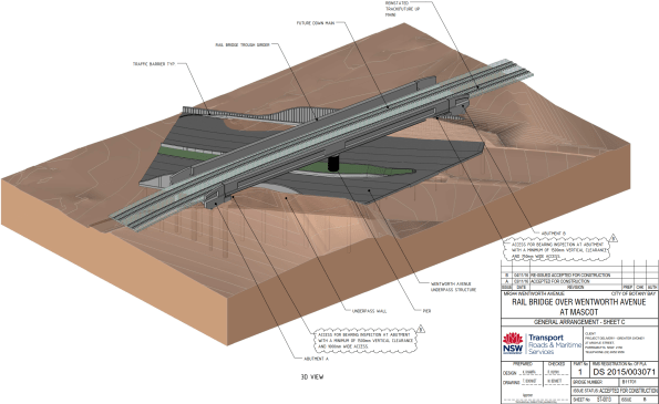
Completed Rail Bridge and Underpass structure
Many thanks.
AHD – Australian Height Datum

James
The calc you show is a bit out- the number of flow tubes is 5 and the number of drops (you show) is 13
However the output is fairly insensitive to this and the flow is less than 1/50th of a litres per second. You would double this for the corners
A 50mm pipe with a submersible pump in a sump lifting through 5m would give 3l/s or so – so barely any dewatering required?
James – I see you have quoted the permeability from elsewhere. Do you know where this came from or how reliable it is? It seems a sensible figure given the description but remember that the flow rate is sensitive to the permeability.
Just spoke to JE and he pointed out that I’m 1000 out…quite right it’s 10l/s
Holy hell!
So a little risk in k and 3D flow ( coffer) and we get to 50l/s
and a need for a serious scheme
Oooooop!
James,
Interesting. When the design was carried out for the sheet piles, was the ground water regime not thought about? Is it on the designers CDM Risk Register?
Perhaps this should be given to Phase 1 for their Ex Cofferdam!?
James, I hope you are well and haven’t picked up the local lingo. My geography is poor, was sort of rainfall do you get? Is flooding of the underpass acceptable during rainfall? What scope is there for grouting? I.e. Changing the permeability? Not cheap though.
JY – Similar to the Lambeth Group in London, much research has been conducted on the Botany Sands and construction methods within them as they cover most of south eastern Sydney. Their permeability ranges from 1 x10⁻⁴ to 3 x10⁻⁴ depending upon density. In-situ tests have been performed on site using falling head, rising head and Packer tests which after consultation with John I believe to give a fairly reliable result. As the excavation is taking place under an existing rail embankment, it is possible that cyclic loading from trains will have reduced the voids ratio, therefore reducing permeability. Although I am not sure how deep these effects will go. I would hypothesis that 3×10⁻⁴ is a conservative value of k if this case.
HM – The sheet piles were designed from factors from an initial GI report. The methodology for construction of the cofferdam mentions, ‘Adjust groundwater levels within excavation accordingly to suit excavation depth.’ No more information is given on the dewatering methodology.
I am proposing installing the spears in the recesses of the sheet pile wall to allow formwork to be fitted to the front. This would give a cc spacing of 1200mm. The header main would then be placed above the construction joint upto 6m higher on the sheet pile wall.
Similar to Ex Coffer there is a drawdown / settlement issue. The Client deems their biggest risk to be drawdown and has specified that ‘the dewatering system must be designed to limit drawdown immediately adjacent to the rear of the temporary retaining structures to a maximum of 15 mm, reducing to a maximum of 10 mm at the nearest residential and commercial buildings and at the canal’. The values of maximum drawdown of water levels given in the specification are extremely low and in practice unrealistic. Potential damage to buildings and other structures is caused by settlements associated with drawdown, rather than the drawdown values. In addition the amount of damage that will occur is related to the differential settlement that occurs across a structure rather than the settlement magnitude.
BB – Hey Brado, they abbreviate everything out here and put an ‘o’ on the end, then you’re basically an Ozzy.
You’ll be pleased to know that it actually rains over double the amount in Sydney annually than London. Although when it does rain, its causes flash flooding hence the Underpass requires a sump pump to drain it. I am currently procuring a waterproof membrane system to use in the underpass.
I have examined the use of grouting within the coffer, this would have to be completed prior to the construction of the rail bridge to allow the grouting rig access. The Underpass contains screws piles to hold it down as it will be buoyant beneath the water table, these are installed once excavation is complete. The concern is the screw piles breach the integrity of the grouting layer which could cause leakages. The system would lower the permeability but a dewatering system would still be required. An initial cost I was quoted was $Aus 1.5 million. It is a relatively new technology in Australia with only a handful of successful project achieved over here so far.