Archive
Temporary Works
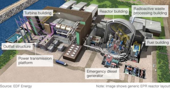
I am working in a team of 10 for the JV that has the main civils contract for Hinkley Point C. Bouygues-Laing O’Rourke (Bylor) are responsible for the structure(s) that contain the nuclear gubbins for the 3200 MWe reactors, cooling systems, and ancillary buildings. Currently circa. £2bn of contracted scope, and rising.
The TW office responds to requests for scaffold, formwork, lifting calculations and other curios from site on an ad-hoc basis. They liaise in advance with the pre-construction team (working mostly out of Paris) to design formwork and falsework systems along with bases for the 40-50 tower cranes to be installed. Large volume packages are let and managed by the TW team to supply chain companies like Sateco, Peri, Doka and Hunnebeck.
I just completed my first task which was re-working some calculations for reinforcement cage lifting and issuing the new lift schedule to site. Not quite a flume I know Ed! The cages were for the reactor inner containment structure which consists of a pre-stressed ring and conventional reinforced concrete. This forms the lower wall of the reactor building(s). I can’t put up any decent drawings or models, unfortunately. The re-working was required as the method of installation changed, separating the cages into smaller lifts.
I was surprised at the factor of safety of 1.35 x 1.2 was applied for what is 3 crane lifts. Onto the wagon, off the wagon and turned vertically prior to installation. By using some steel designers manual/StaadPro/standard beam formula I managed to reduce quite a lot of the welding on each cage. The number of ties on the cage was the critical case.
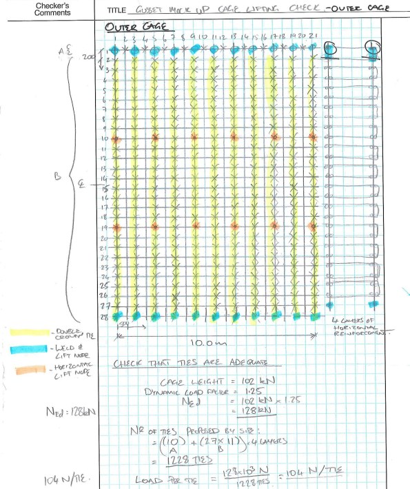
Proposed tie and weld arrangement. Still less conservative than the original design.
Ties themselves are difficult to quantify although tensile testing exists. An assumed SWL of 254N (25kg) gave a FoS of 8 from tensile test results. I couldn’t find out where that SWL was taken from. It seems rightly high in FoS terms given the risk of corrosion, human error in tying and damage. Future testing of tied wire is in the offing which should provide data for my TMR on the subject. I expect the variance between samples to be greater, and still quite difficult to pin down. However, any improvement in capacity reduces the amount of work for the steel fixers which equals fewer hunchbacks and less knackered wrists!
Working in the office is a noticeable step change from the site. Namely, that, a lot of people wear headphones all day and there are fewer threats of violence or general harassment. When I told the animals on site that I was going to work in TW they said that I’d be responsible for adding zeros to the budget and making things difficult to construct. On reviewing a small work package for welding to reinforcing cages I have observed how this can occur. I have also seen how easy it is to specify something that is overdesigned or even unsafe to construct. Particularly as they do not see many pairs of eyes before heading out the door.
I’ll hopefully have something more coherent and of note to post soon.
Dan
Transition to the USACE Design Office at 2 Hopkins Plaza
With the cobwebs of Christmas and New Year finally gone (along with AER 4) I thought it was about time I wrote an update of my attachment in the USA.
As of mid-December, I was able to handover the majority of my work at the East Campus in Fort Meade to a young and overly energetic intern. With the majority of the project complete and the main effort shifted to the architectural team’s handover of internal rooms and the mechanical team’s underfloor air distribution (UFAD) testing and commissioning, I almost felt a little sorry for the guy – arriving with so little civil works left to complete. From me, he inherited responsibility for:
- Processing and distributing the daily submittals from the contractor,
- Supervising the production of as-built data for the site’s sustainable storm water management (SWM) systems.
- Supervising the placement of internal roads (a combination of pervious, and impervious concrete), and
- Supervising the contractor’s application of erosion and sediment controls on behalf of the State’s department of the environment.
Surprisingly, he seemed a little overwhelmed and concerned that some of the work allowed him to make decisions and issue site instructions. I hadn’t realised how accustomed the army and such a short time spent on Phase 2 had made me to making decisions and accepting responsibility. In his defence, I suppose he hadn’t even been qualified for a year and speaking to him later, it became apparent that USACE severely warns them against obligating the government to anything not already in a contract (for those just finishing up on Phase 1, remember this and don’t be overly critical of yourself when it comes to judging attribute competences).
Closer to the present, January in Baltimore has been an intense combination of very, very, very cold weather and also my re-introduction to technical engineering. After a full 8 months of performing QA of “horizontal construction” (drainage and grading, pavements and slab-on-grade with a little bit of footing work), I have commenced Phase 3 by assuming a design engineer role in Baltimore City. From now until the end of June, the intent is to work within the USACE Site Development Section performing a broad range of infrastructure and site design tasks. A small hierarchy made for AER4 showing my location within what is effectively USACE’s Baltimore design office is shown below:
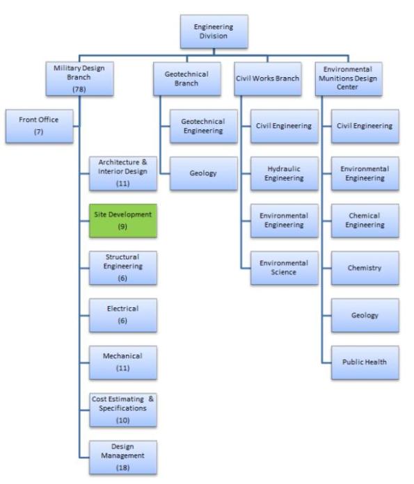
The parent organisation of the site development section is the Military Design Branch. These approx. 80 personnel design and supervise the construction of DoD facilities across an area of responsibility approximately similar in size to England and Wales. This work includes “in-house” design for DoD organisations and the technical review of in-progress or completed Architect/Engineer designs by third parties.
My main role includes a number of small tasks that essentially see me designing sustainable drainage solutions for DoD installations. The scale varies from designing systems to manage surface water volumes from design storms (normally the 1 in 2 and the 1 in 100 year storms) to designing retrofits that ensure pollutant loads such as Nitrogen, Phosphorous, and total suspended solids are reduced in the “first flush” of 1.0 inches of rainfall.
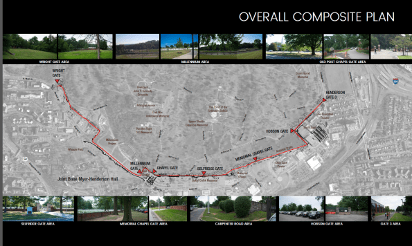
I will also soon be designing stormwater management aspects of a 2km perimeter fence that is going to be installed in Ft Myers, not far from DC and the Pentagon. Strangely for the US military, a large section of the perimeter since the late 19th century has been a 4-ft high stone wall. A number of recent incidents have occurred involving French tourists getting lost in the neighbouring Arlington National Cemetary and ‘hopping the wall’ to get to what they think is a nearby strip-mall. Unsurprisingly, the DoD has decided it may be time to increase the level of security. In addition to designing the profile and construction details of the fence plus integrated cameras etc… the project also requires consideration of bisecting drainage channels, the construction of a new car park and creation of additional SWM to account for the increase in impervious surface areas.
As we’re still waiting for the client to decide on the contract vehicle for this work, USACE and I are still a little unsure on the level of design work required but we hope to get an answer fairly soon. Until then, here are some unclassified graphics pilfered (with permission) from the department’s project folder (yes, that is a design engineer’s attempt at doing before and after concept work using photo-shop):


Aquatar & Icon Tower
I thought it would be interesting to briefly post about a project I’m working on as it is a little different:
Aquatar is a brand new waterpark development on Etaifan Island in Doha, Qatar. The client is Katara Hospitality, a global developer of the Emir of Qatar. Atkins are delivering the concept design. The project involves 21 rides and attractions, a 75m iconic tower ride, themed bridges and various dry attractions. The waterpark site is located on Qetaifan Island, an area of recently reclaimed land on the coast north of Doha. This means the buildings will be subject to high thermal and wind loads, seismic actions and durability requirements of a marine environment.
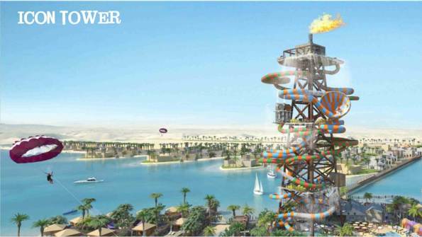
I am responsible for the design of the Icon Tower which will be a braced steel frame with an internal reinforced concrete core. The tower will take the form of an offshore oil-rig type structure as seen in the picture above and in line with the theming of the waterpark. The height of the building will be around 75m with a base width of around 25m. The tower will have many water rides twisting around and through it meaning that saving space is essential to maximize the flumes passing through. These rides will be supported back to the primary structure by secondary steel bracketry (by others). The tower is located offshore on a separate reclaimed island (Icon Island). Lateral stability will be achieved by a combination of the core walls and action of the braced steel frame that will withstand all design horizontal loads from wind and seismic actions. Gravity loads consisting of self-weight of the structure, super imposed dead loads and live loads will be transferred via the floor plates to the braced steel structure and core, to the structure foundation.
![]()
Slide layout. Currently the shape and direction that the slides will go in is not defined. For the flume slides the average angle of a slope is 1:11. The actual path of the slides will be decided by the ride manufacture and will not come at this stage. What I am doing is considering average loads on the structure whilst waiting for a water slide manufacturer to provide me with loadings. The flumes will go around and also through the tower therefore I need to leave sufficient room between the tower bracing to allow this to happen.
Quick calc. Between floors 2 and 3 at 34m and 50m respectively, there are 5 flumes. Assuming each flume is 2m in diameter, and considering the most simple ride that goes in a circle around the circumference of the tower (they will be more complicated that this and this will cause even greater issues, however simply for this calc they go around the outside). The circumference at the bottom is roughly 78.5m. The height difference between 34m and 50m is 16m. At a 1:11 slope the length of flume needed to go from 34m to 18m is 176m. This means that the flume will go 2.24 times around the structure (176/78.5) within this 16m floor level difference. A single flume will take up 4.48m (2m high x 2.24 loops) of surface area over the structure of the 16m. 5 Flumes will therefore take up 22.4m of the 16m available. Tubes will therefore have to be hanging off the structure 2 wide in some locations, and will need to go through the structure multiple times in other locations. Space may be an issue.
This highlights some of the complexity we are working with and I’m sure will provide good blog material in the coming months. Now I’m off to dabble in some seismic loading.
Phase 3 – getting the geek on!!
Hi all,
Merry Christmas, I trust like me everyone had intentions to do loads of thesis but ended up doing none.
Getting a little bored of working for a management contractor I decided to move to phase 3 mid November. I though now would be a good time to give a little update.
I’ve started at a small office which have recently branched out from Australia into the London market called BG&E. I haven’t yet worked out what that stands for, for those interested here is the website.
There are 9 in the office, 4 structural engineers, 1 BIM technician, 1 CAD technician, 2 RC detailers and me. So far the office has been doing temporary works for some of the big London contractors and some mid rise residential developments in Cyprus.
Since starting, I have been getting bits of work but as can be expected nothing substantial. I’ve outlined what type of stuff I’ve been doing.
Task 1 – Reinforcement rates
Part of a wider package with Getjar, as a second checker I used a mixture of RC intents and details to calculate tonnages for costing as part of a tender return.
Task 2 – Transfer Beams
The Broadway, London is a resi/commercial development with 6 buildings between 14 – 20 stories. The structural engineers, RBG, have detailed a steel section encased in RC as a transfer structure for a line of columns which go the hight of the structure. The step that the beams make is an architectural feature of the building creating large lobbies, see the section through below.
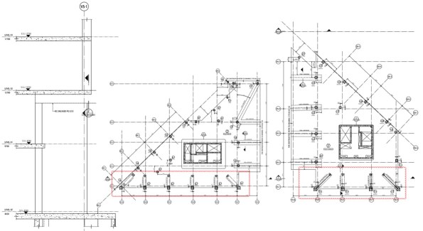
The issue was the contractors crane strategy did not have the lift capacity/radius to lift in the transfer beams. So they engages BG&E to conduct an option study, which was then given to me. There was no information on column loads, just the GAs and floor load diagrams. Unfortunately for me, the column tributary areas are different for each column and also the loads. So I did a column run-down using load reduction permitted in EC1 to get the loads at the base of the supported column. I then used a software called RAPT to ‘play’ with possible options. The most effective solution would have been to increase the depth of the beam and use normal reinforcement, however generally beams cannot be increased in depth due to the other trades. So I increased the width of the beam to 1200mm and it worked with 3 layers of 32s @ 100 (in the bottom), this was proposed to the contractor and we wait for further work. Clearly PT could have been used, but the it is not clear if the floor plates will be PT as they are c300-350mm which is thick for the spans.
Task 3 – Climbing Screens
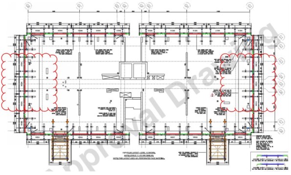
Wembley Park, is a large resi development to the left of Wembley Stadium for those who have been recently. The contractor has won the job and is trying to work out their climbing screen and back propping strategy, the climbing screens can be seen below. This seems a little late to me, how much floor back propping is required and how quickly it can be struck must surely be known to form a programme. Unless it is a guess….
Getjar ask BG&E to conduct a concept study to see what is required for the climbing screens. Again the RC intent was not available as the design is not that advanced, all that was available was the floor plans and loading diagrams. Looking at the typical floor layout it was clear that there were three different spans. Knowing that the RC slabs would be designed for the loads in the diagrams, i.e. permanent case. I built the spans in RAPT (programme) and calculated the forces and reinforcement required. I then used this to compare to the construction case with the loading from back propping, climbing screens and a construction LL.
This showed that the climbing screens did not need any additional back propping, if the loads where not applied at the same times as the back propping to construct the wet deck. This is unlikely, as the buildings a residential the SDL and LL are low, 1.5Kpa each. The 250mm RC slab exerts a back propping load significantly larger than this and would need back propping over at least two floors. I calculated that for the loads to be combined the reinforcement would need increasing locally by up to 15% above that required in the perm case. It is now up to Getjar to do a cost exercise, material cost v programme to see which is preferred.
As a side note I also check deflections to ensure deflections under construction loading where not excessive. Whilst doing so I noticed that one of the larger spans was deflecting 30mm under permeant loads which is over span/250, which would be bad for internal finishes. I raised this to the contractor and this may come back to BG&E to design a PT slab for this area.
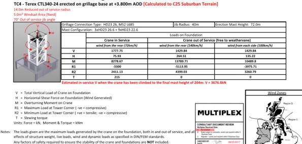
Task 4 – Tower Crane Grillage Cat 3 Check
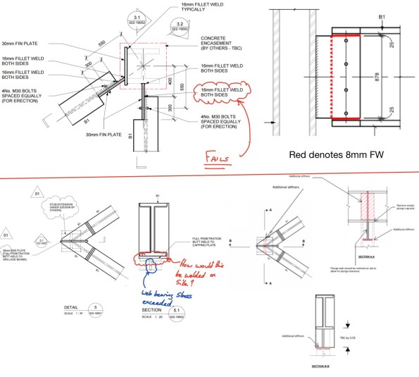
The foundations for tower cranes are generally considered temporary works and as such fall under the guidance of BS 5975. The level of the required design check is outlined generally on the complexity and consequence of a failure, the category’s can be seen below.
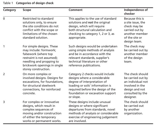
My previous project, One Nine Elms has 5 tower cranes, all supported off grillage which is more complex than normal, I have discussed one at length in a previous post. Clearly the consequence of a failure could be dire, for those with a strong stomach YouTube ‘tower crane collapse Mecca’. It is also bad for business, failures are very public affairs and to make them worst developers/main contractors like to put their company logo on the crane. Anyway, a cat 3 check should be conduct by a person outside of the organisation which did the design. The check should be done without the calculations, just the drawings and any pertinent information, loading etc etc. This task was given to me with the direction to see how far I get…… shit. I was given some information about the crane and Carey’s design drawings.
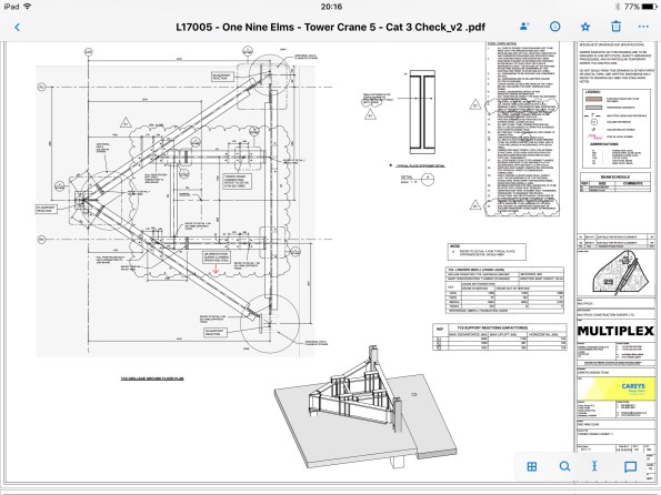
My first start was to check Carey’s had used the correct loads from the crane supplier, it was slightly concerning to find they had missed the most onerous case a storm hitting the front of the jib. I built the steel grillage in a software called Microstran (similar to STAAD) and applied the loads with a number of different combinations to get forces and deflections. I then realised I have forgotten everything Neil taught us about steel and spent a day going back through section and member checks by hand, the software also does a check which it useful. Clearly somebody sits in the crane cab so a large differential deflections between the legs gets amplified higher up. I also believe the crane suppliers factor up the loads they provide, as a way of reducing deflections to stop Pdelta effects.
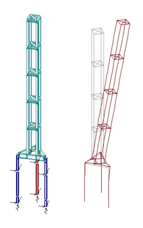
By far the most difficult check was the connections, with my main issue being whether to fix or pin the members at the joint. I found the 16mm FW on the fin plate insufficient by some margin in either case and suggested an alternative solution. The solution (see below top) uses and 8mm FW which can also be done with one pass so Saving labour costs. In checking the apex type of connection I found that the plate welded to the plunge column plate resulted in a bearing stress great than the capacity of the section and would also be difficult to weld on site. After some head scratching and advice I came to the solution below.
Quite a bit if stuff in a couple of weeks and I am learning lots quickly. One thing I have noticed is that the engineers do almost everything on some form of analysis software, Excel and Bluebeam with very little being done by hand.
I hope I haven’t bored everybody to much but you already know I’m a geek.
Brad
James, these are the loads supplier by Select for a 70m tower crane. The overturning moment drops to almost nothing when the crane is tied.