Archive
Aquatar & Icon Tower
I thought it would be interesting to briefly post about a project I’m working on as it is a little different:
Aquatar is a brand new waterpark development on Etaifan Island in Doha, Qatar. The client is Katara Hospitality, a global developer of the Emir of Qatar. Atkins are delivering the concept design. The project involves 21 rides and attractions, a 75m iconic tower ride, themed bridges and various dry attractions. The waterpark site is located on Qetaifan Island, an area of recently reclaimed land on the coast north of Doha. This means the buildings will be subject to high thermal and wind loads, seismic actions and durability requirements of a marine environment.
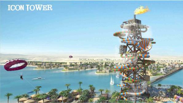
I am responsible for the design of the Icon Tower which will be a braced steel frame with an internal reinforced concrete core. The tower will take the form of an offshore oil-rig type structure as seen in the picture above and in line with the theming of the waterpark. The height of the building will be around 75m with a base width of around 25m. The tower will have many water rides twisting around and through it meaning that saving space is essential to maximize the flumes passing through. These rides will be supported back to the primary structure by secondary steel bracketry (by others). The tower is located offshore on a separate reclaimed island (Icon Island). Lateral stability will be achieved by a combination of the core walls and action of the braced steel frame that will withstand all design horizontal loads from wind and seismic actions. Gravity loads consisting of self-weight of the structure, super imposed dead loads and live loads will be transferred via the floor plates to the braced steel structure and core, to the structure foundation.
![]()
Slide layout. Currently the shape and direction that the slides will go in is not defined. For the flume slides the average angle of a slope is 1:11. The actual path of the slides will be decided by the ride manufacture and will not come at this stage. What I am doing is considering average loads on the structure whilst waiting for a water slide manufacturer to provide me with loadings. The flumes will go around and also through the tower therefore I need to leave sufficient room between the tower bracing to allow this to happen.
Quick calc. Between floors 2 and 3 at 34m and 50m respectively, there are 5 flumes. Assuming each flume is 2m in diameter, and considering the most simple ride that goes in a circle around the circumference of the tower (they will be more complicated that this and this will cause even greater issues, however simply for this calc they go around the outside). The circumference at the bottom is roughly 78.5m. The height difference between 34m and 50m is 16m. At a 1:11 slope the length of flume needed to go from 34m to 18m is 176m. This means that the flume will go 2.24 times around the structure (176/78.5) within this 16m floor level difference. A single flume will take up 4.48m (2m high x 2.24 loops) of surface area over the structure of the 16m. 5 Flumes will therefore take up 22.4m of the 16m available. Tubes will therefore have to be hanging off the structure 2 wide in some locations, and will need to go through the structure multiple times in other locations. Space may be an issue.
This highlights some of the complexity we are working with and I’m sure will provide good blog material in the coming months. Now I’m off to dabble in some seismic loading.
