Archive
Phase 3 – Structures Team at RBG
5 weeks down and hopefully something of value to report. It took several weeks for my brain to warm up.
Interesting to see the content of Brad and Dan’s work. The temporary works environment looks excellent in terms of variety and volume of small problems to solve.
I am now working for Robert Bird Group (RBG) in Sydney within one of their structures teams. The Sydney office contains 2 structures teams, a civil design team, and a construction engineering team (temporary works and construction methodology). I am currently working on 2 projects; University of Wollongong (UoW) and Blacktown and Mount Druitt Hospital (BMDH). UoW is in the tender design phase and BMDH is under construction.
The structures team is managed by a principal engineer, with the support of 3 associate engineers. RBG policy dictates that all associate engineers and above must be chartered engineers. Work packages are assigned to the engineers, including myself, at the team resource meeting which is held every Monday morning.
My responsibilities to date:
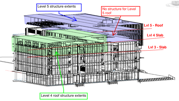
Task 1. UoW – Structural Steel Frame design on Levels 4 & 5. I was tasked to develop the concept designs for the entire level 4 and 5 structural steel roofs. In the initial stages, I had to scrutinise the architectural model in Revit as well as the architectural floor plans to produce some initial layouts for a frame. The aim was to create a frame layout that would correspond with the Architect’s floor plan but, also achieve continuity of load run-down through to the concrete frame to avoid load transfer. The level 4 roof was to be built off the level 3 slab, and the level 5 roof off the level 4 slab. You can see the extents of the steel frames for level 4 and 5 in RBG’s structural BIM model below (you can see that level 5 had no structural elements at this stage). My initial layouts were incorporated into the BIM model and the in-house draftsman created some hasty level 4 and 5 general arrangements (GA) for further design development.
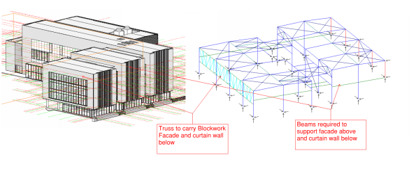
In order to simplify the analysis and design, I decided to consider level 4 & 5 separately. I used a software package called Microstran (I agree with Brad, much easier than STAAD) to complete the analysis for the indeterminate frame. The biggest challenge was ensuring that lateral stability was provided and that the frame included members to support the various architectural features (e.g. curtain walls and façade). I finally opted for horizontal and vertical bracing in order to provide lateral stability (loads eventually running back into structural slab). The image below shows my Microstran model for level 4 and the various structural elements that had to be included to support some of the architectural features.
 To create a working model, the nodes and members had to be modelled accurately in order to complete analysis. Deciding whether a connection was to be pinned or fixed was very challenging. The process helped me understand how the overall structure and individual members were behaving (e.g. tension only members, what the different connection types would be and what forces could be transferred). To simulate the interaction between the frames on level 4 and 5, I modelled the connection as pin supports.
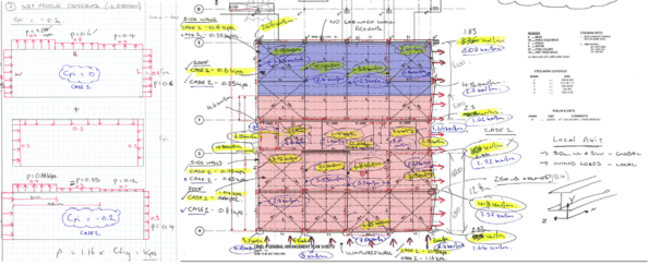
Once the associate engineer was satisfied that my model was stable, I then had to calculate the actions and create the design load combinations for the model (22 in total). This included the calculation of wind actions using Australian Standard (AS) 1170.2.2011: Wind Actions. The process was similar to EC; you work out the design pressure and your net pressure coefficients to get a KPa value (extract from my calculations below).
After calculating the actions on the structure, I then assigned section classifications to each member in the model. I started by considering the primary rafter and modelled it as a SS beam to get a ballpark BM. With the primary member assigned, I worked through the structure and reduced the section geometry as I went. I had to go back and change some of the sections, as RBG will typically use particular sections for different purposes (e.g. CHS/SHS for struts and EA for ties). With more experience, this process would be more intuitive. The image below shows my final model for level 4, the different section classifications are indicated by different colours (left image). The image on the right is my final analysis and shows the BM envelope for all load combinations. I used the results to complete strength and serviceability checks on the sections I had chosen. Australia didn’t completely copy the English on this one, they have the RED BOOK for their steel section properties and capacities. Deflections and bending capacities were satisfactory (Span/500 was used to be conservative). I did have to incorporate some fly bracing (restraints) to reduce the effective length of the main rafters; to prevent buckling in the wind suction case.

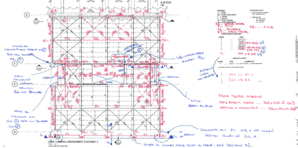
RBG subcontract the final production of structural drawings to RAMTECH software solutions in India. Therefore, I had to produce some marked up GAs and elevations to communicate my design output for final drafting (see examples of my work below). The final drawings will be issued to the competing contractors, via the client, to assist with pricing the job for tender submissions.

Task 2. BMDH – Precast concrete façade inspections. I was also tasked with overseeing the final approval and inspection of some pre-cast concrete façade panels on the BMDH. The panels are essentially SS slabs on the outside of the building. They are supported at the top of the panel by a corbel that sits on the structural slab and is pinned by a dowel connection (see image below).
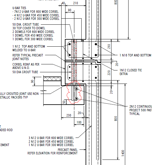
The design had already been completed for the panels and I just needed to check the details during my inspection. However, I wanted to understand how the panels were behaving and did some simple analysis to identify where the critical points for inspection were. I deducted that the shear load in the dowel connections was critical and that the critical BM would be in the corner of the panel (FBD and quick analysis below). The wind action would also create biaxial bending (so vertical and horizontal reo required in panel).


The panels were being constructed by Hanson in their factory just outside Sydney. The Architect (Jacobs) and Contractor (AW Edwards) were also present during the inspection. The reinforcement was satisfactory; however, honeycombing was identified in some of the corbels, which reduced the cover and durability of the section. Hanson will now provide a product specification and methodology for patching in those areas.


